Drive force transmitting apparatus for vehicle

a technology for transmitting apparatus and driving force, which is applied in the direction of mechanical control devices, process and machine control, instruments, etc., can solve the problems of increasing the size of the transmission case, the inability of parking lock apparatus to apply to hybrid vehicles, and the increase in the total weight of the transmission, so as to reduce the cost and weight of the drive force transmitting apparatus, the effect of greatly reducing the number of parts

Inactive Publication Date: 2007-11-29
HONDA MOTOR CO LTD
View PDF1 Cites 35 Cited by
  • Summary
  • Abstract
  • Description
  • Claims
  • Application Information

AI Technical Summary

Benefits of technology

[0009]With this arrangement, the drive force transmitting apparatus includes the actuator mechanism capable of selectively operating the clutch mechanism and the parking mechanism. Accordingly, as compared with the case that any dedicated selector apparatus is provided for each mechanism, the number of parts can be greatly reduced to thereby greatly reduce the cost and weight of the drive force transmitting apparatus.
[0010]Preferably, the actuator mechanism can switch among a first condition where the clutch mechanism is engaged to connect the drive force transmitting path, and the parking mechanism is disengaged to cancel a parking lock condition where the drive shaft is fixed in rotation; a second condition where the clutch mechanism is disengaged to disconnect the drive force transm...

Problems solved by technology

In the parking lock apparatus disclosed in Japanese Patent Laid-open No. sho 59-222668, however, the parking shaft for mounting the parking gear must be specially added, causing an increase in size of the transmis...

Method used


Image

  • Drive force transmitting apparatus for vehicle
  • Drive force transmitting apparatus for vehicle
  • Drive force transmitting apparatus for vehicle

Examples


Embodiment Construction

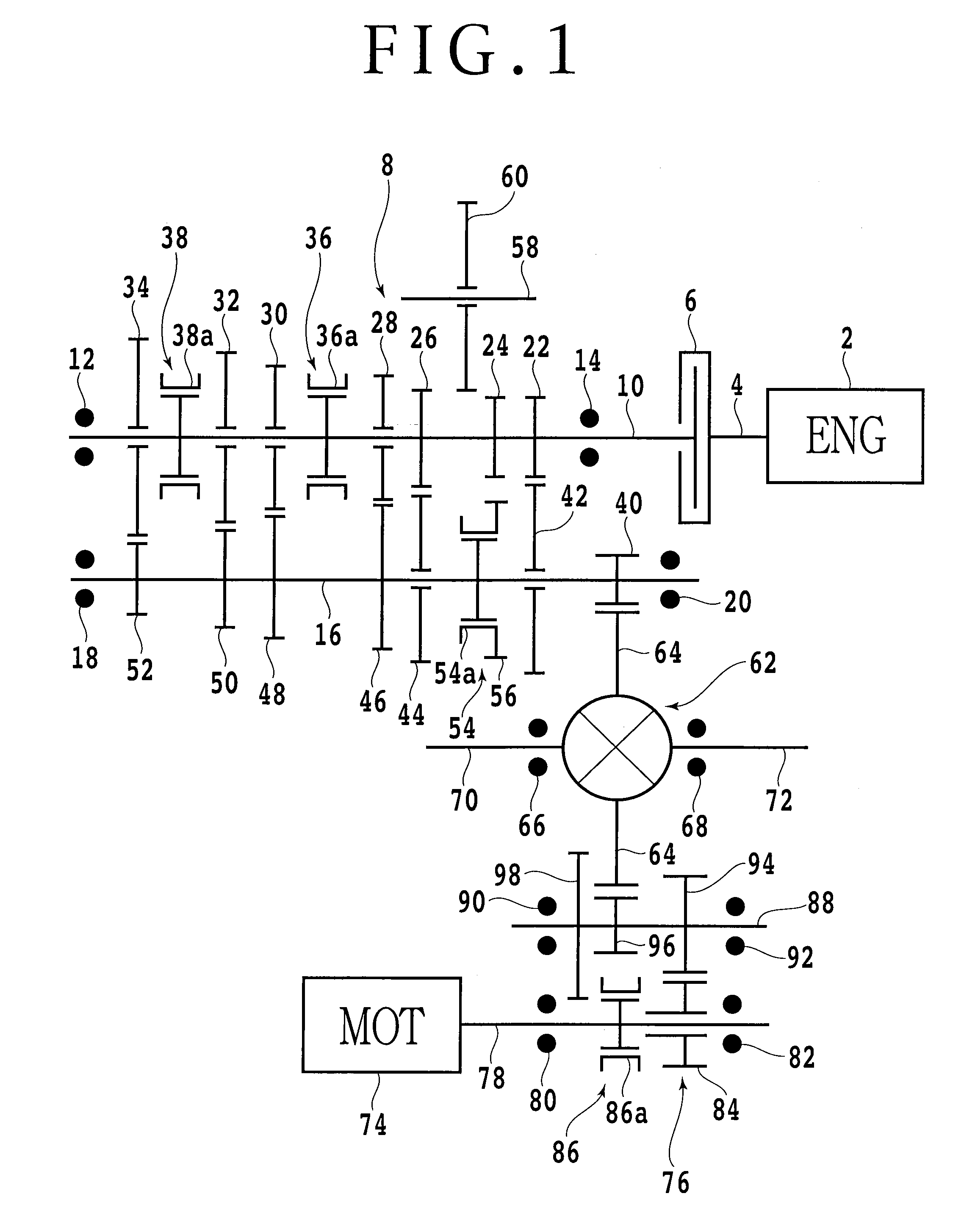
[0020]FIG. 1 is a skeleton diagram of a drive force transmitting apparatus for a hybrid vehicle according to a preferred embodiment of the present invention. A crankshaft 4 of an engine 2 is connected to a clutch 6. A drive force generated by the engine 2 is input to a main shaft (input shaft) 10 of a transmission 8 by engaging the clutch 6. The configuration of the clutch 6 may be of such a type that it is manually disengaged by depressing a clutch pedal or automatically disengaged by an actuator. The main shaft 10 of the transmission 8 is rotatably supported by a pair of bearings 12 and 14. A counter shaft (output shaft) 16 extending parallel to the main shaft 10 is also rotatably supported by a pair of bearings 18 and 20.

[0021]There are provided on the main shaft 10 a first speed drive gear 22, a reverse drive gear 24, a second speed drive gear 26, a third speed drive gear 28, a 3-4 speed synchromesh mechanism 36, a fourth speed drive gear 30, a fifth speed drive gear 32, a 5-6 s...


PUM


Abstract

A drive force transmitting apparatus for a vehicle including a drive source, a drive force transmitting path adapted to be connected to a drive shaft to transmit a drive force from the drive source to the drive shaft, and a clutch mechanism capable of connecting and disconnecting the drive force transmitting path. The drive force transmitting apparatus further includes a parking mechanism provided in the drive force transmitting path and capable of stopping the rotation of the drive shaft and an actuator mechanism capable of selectively operating the clutch mechanism and the parking mechanism.

Description

BACKGROUND OF THE INVENTION[0001]1. Field of the Invention[0002]The present invention relates to a drive force transmitting apparatus for a vehicle including a drive force connecting and disconnecting mechanism (clutch mechanism) and a parking mechanism.[0003]2. Description of the Related Art[0004]A parking lock apparatus in a vehicle having a continuously variable transmission (CVT) is disclosed in Japanese Patent Laid-open No. Sho 59-222668. The parking lock apparatus disclosed in this publication is provided in an auxiliary transmission added to the CVT. This auxiliary transmission includes an input shaft, an output shaft, and an intermediate shaft (reverse idler shaft) and further includes a parking shaft extending parallel to each shaft mentioned above and nonrotatably mounted to a transmission case.[0005]A parking gear is nonrotatably mounted on this parking shaft. A reverse driven gear is axially slidably provided on the output shaft. In effecting a parking lock condition, th...

Claims


Application Information

Patent Timeline
IPC IPC(8): B60T1/06F16H63/34
CPCF16H63/304F16H63/3416F16H63/3466Y10T74/19251Y10T74/2003Y10T74/20183F16H2063/3056
Inventor SAITOH, NORIAKI
Owner HONDA MOTOR CO LTD
Why Eureka
Try Eureka