Control device for controlling in-vehicle unit

a technology for controlling devices and in-vehicle units, applied in signalling/lighting devices, vehicle components, optical signalling, etc., can solve problems such as unsuitable drivers, devices disclosed, and documents that involve problems, and achieve the effect of dramatically increasing the operation model of in-vehicle units

Inactive Publication Date: 2007-11-29
DENSO CORP
View PDF2 Cites 46 Cited by
  • Summary
  • Abstract
  • Description
  • Claims
  • Application Information

AI Technical Summary

Benefits of technology

[0072] Thus, the chance to learn the in-vehicle unit operation model is dramatically increased as with a control device as an aspect of the present invention. Further, it is possible to add a variable indicting a situation not contained in

Problems solved by technology

However, the devices disclosed in the above documents involve problems.
When predetermined control is carried out under a predetermined condition and the driver does not accept the control, that condition is not suitable for the driver and should not be

Method used


Image

  • Control device for controlling in-vehicle unit
  • Control device for controlling in-vehicle unit
  • Control device for controlling in-vehicle unit

Examples


first embodiment

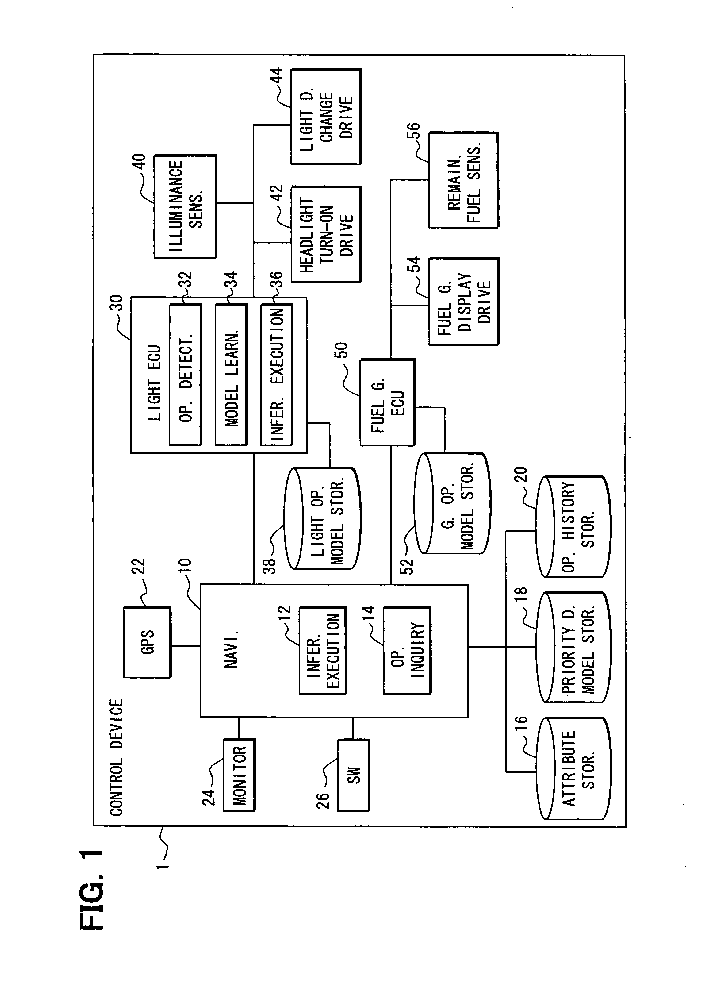
[0099]FIG. 1 is a drawing illustrating the configuration of a control device 1 that controls in-vehicle units mounted in a vehicle, in this embodiment. In this embodiment, as illustrated in FIG. 1, the vehicle includes an illuminance sensor 40, a headlight turn-on drive unit 42, and a light direction change drive unit 44. The illuminance sensor 40 detects the lightness of exterior and is installed on, for example, top of the vehicle. These in-vehicle units related to lights are all connected to a light ECU (Electronic Control Unit) 30 and controlled by the light ECU 30.

[0100] The light ECU 30 includes an operation detection unit 32, a model learning unit 34, and an inference execution unit 36. The operation detection unit 32 has a function of detecting the operations of the in-vehicle units controlled by the light ECU 30. An example will be taken. When the headlights are turned on by the headlight turn-on drive unit 42, the operation detection unit 32 detects that the headlights ha...

second embodiment

[0147] Description will be given to a control device in a second embodiment of the invention. The control device in the second embodiment and the control device 1 in the first embodiment are identical with each other in basic construction (Refer to FIG. 1). In addition to the construction of the control device 1 in the first embodiment in which the presence or absence of operation needs is determined with respect to each in-vehicle unit, the control device in the second embodiment has a construction for controlling multiple in-vehicle units that are often operated at the same time.

[0148]FIG. 11A and FIG. 11B are drawings illustrating examples of service templates that define the operations of in-vehicle units that are often simultaneously performed in the control device in the second embodiment. The GS operation template illustrated in FIG. 11A defines the operations of in-vehicle units that are often simultaneously performed when the vehicle goes into a gas station (hereafter, abb...

third embodiment

[0158]FIG. 14 illustrates the configuration of a control device 3 in a third embodiment of the invention. The control device 3 in the third embodiment is identical with the control device 1 in the first embodiment in basic construction. The control device 3 in the third embodiment is different from the control device 1 in the first embodiment in that the automobile navigation system 10 includes an in-vehicle unit selection unit 70.

[0159] The in-vehicle unit selection unit 70 has a function of performing the following operation: based on various situations notified from individual ECUs, it determines what needs are present in a driver, the vehicle, or the like; and it selects an in-vehicle unit capable of meeting the needs. The “needs” cited here are a particular that motivates the driver to operate each in-vehicle unit and a cause for the occurrence of “operation needs” for each in-vehicle unit. To determine the presence or absence of needs of the driver, the vehicle, or the like f...


PUM


Abstract

A vehicular control device includes (i) situation detection units that detect situation of the vehicle, occupants, or a surrounding area; (ii) a storage unit for storing a model representing association between variables indicating the situation and variables indicating presence or absence of operation needs for each in-vehicle unit, (iii) an inference execution unit that determines presence or absence of the operation needs for each in-vehicle unit using the stored model; (iv) a control unit that controls each in-vehicle unit based on a result of determination by the inference execution unit; (v) an operation detection unit that detects the operation of each in-vehicle unit; and (vi) a model learning unit that learns the stored model using the detected situation when the operation of each in-vehicle unit is detected by the operation detection unit, and an event involving the presence of operation needs for the in-vehicle unit.

Description

CROSS REFERENCE TO RELATED APPLICATION [0001] This application is based on and incorporates herein by reference Japanese Patent Application No. 2006-55902 filed on Mar. 2, 2006. FIELD OF THE INVENTION [0002] The present invention relates to a control device that controls multiple in-vehicle units mounted in a vehicle. BACKGROUND OF THE INVENTION [0003] There are conventionally known devices that control multiple in-vehicle units mounted in a vehicle according to the situation. For example, Patent Document 1 discloses a vehicle agent system in which various units mounted in a vehicle can be effectively utilized without troubling the driver. Here, driver information storing means is provided to beforehand store correspondences between conditions, such as instructions and situations, and in-vehicle units suitable for the conditions. When an instruction is given from a driver or the situation changes, an in-vehicle unit is controlled based on the correspondence stored in the driver info...

Claims


Application Information

Patent Timeline
IPC IPC(8): B60Q1/26
CPCB60W50/06
Inventor HARA, TETSUYAHARA, KOSUKEIWASAKI, HIROTOSHISAKASHITA, MOTOYASU
Owner DENSO CORP
Why Eureka
Try Eureka