Augmented reality-based system and method providing status and control of unmanned vehicles

a technology of augmented reality and unmanned vehicles, applied in process and machine control, aircraft traffic control, instruments, etc., can solve the problems of limited controller's ability to look around, reduced teleoperation, and ineffective application of virtual reality

Active Publication Date: 2007-11-29
HARRIS CORP
View PDF64 Cites 81 Cited by
  • Summary
  • Abstract
  • Description
  • Claims
  • Application Information

AI Technical Summary

Problems solved by technology

In close-range / urban situations, virtual reality cannot effectively be applied, as it requires detailed models of the urban environment which typically do not exist and even if the models existed they would not include new changes (e.g. a car moving in the environment) that are of concern when controlling a UV, particularly through a narrow urban canyon.
Tele-operation reduces the field of view of the controller to the view of the camera attached to the UV and the controller's ability to look around is limited by the speed at which the camera can rotate.
Both the view of the camera and the speed at which it can rotate are inferior to the capabilities of a human.
Thus, peripheral situational awareness is greatly diminished compared to a user actually inside the vehicle.
For example, it is much more difficult to go through a narrow tunnel without hitting the walls by using a camera for the view of the environment than it is with the large field of view and the look-around capability of human vision.
Augmented Virtuality suffers from the same limitations as the above mentioned systems, as the image the human controller sees is limited by the capabilities of the camera and the virtual model of the environment does not account for small changes in the environment.
In addition to the limitations described above, all the above mentioned techniques require the use of remote command centers or at best traditionally large and heavy remote that is carried by an operator to control in most cases a single UV.
In addition, none of these methods allow identifying a specific UV in the real world.
As a consequence, it might be difficult for a user to find a UV in the environment or differentiate two similar UVs which are far away.

Method used


Image

  • Augmented reality-based system and method providing status and control of unmanned vehicles
  • Augmented reality-based system and method providing status and control of unmanned vehicles
  • Augmented reality-based system and method providing status and control of unmanned vehicles

Examples


Embodiment Construction

[0014]The following description, given with respect to the attached drawings, may be better understood with reference to the non-limiting examples of the drawing, wherein the drawings show:

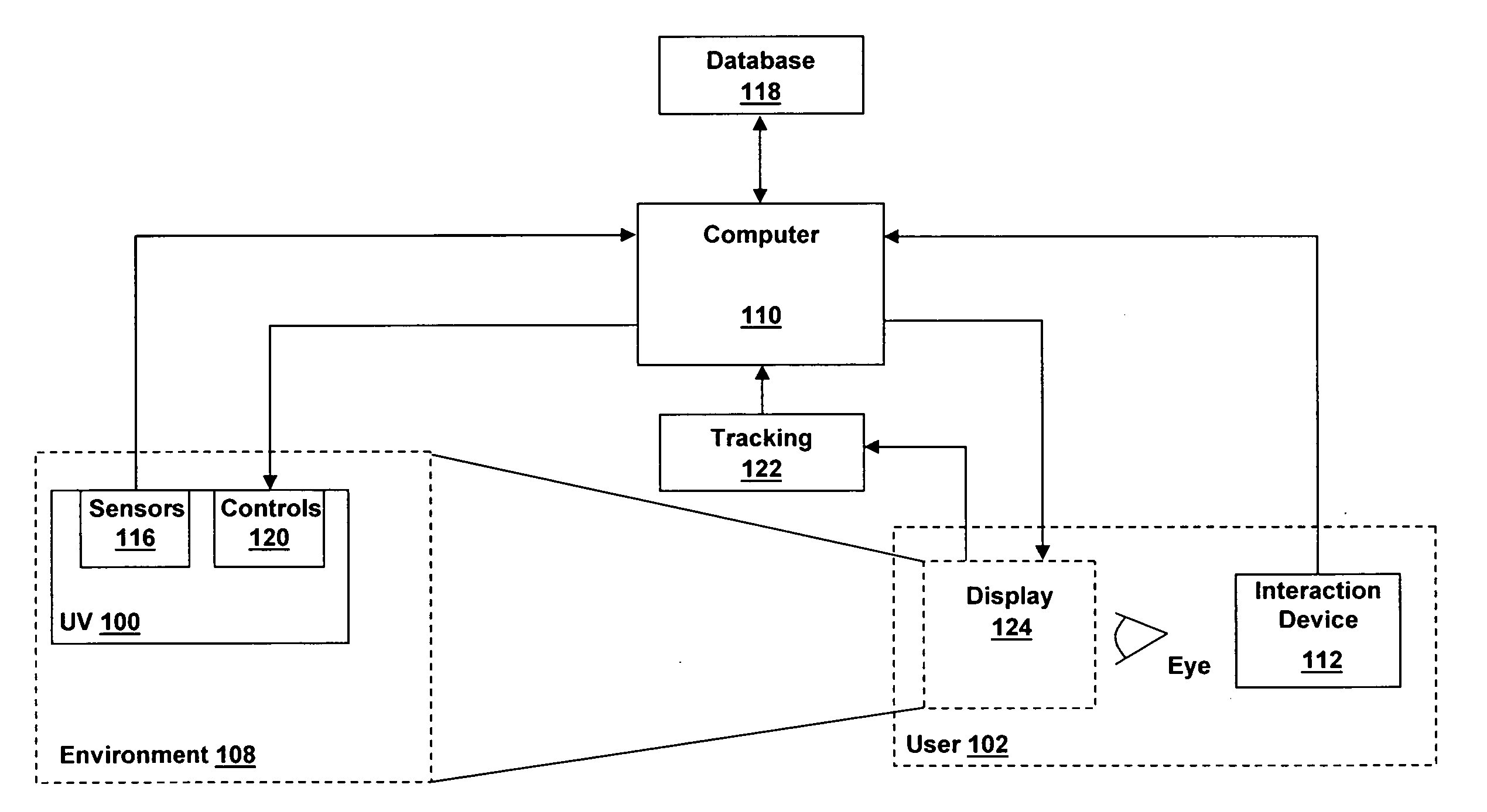
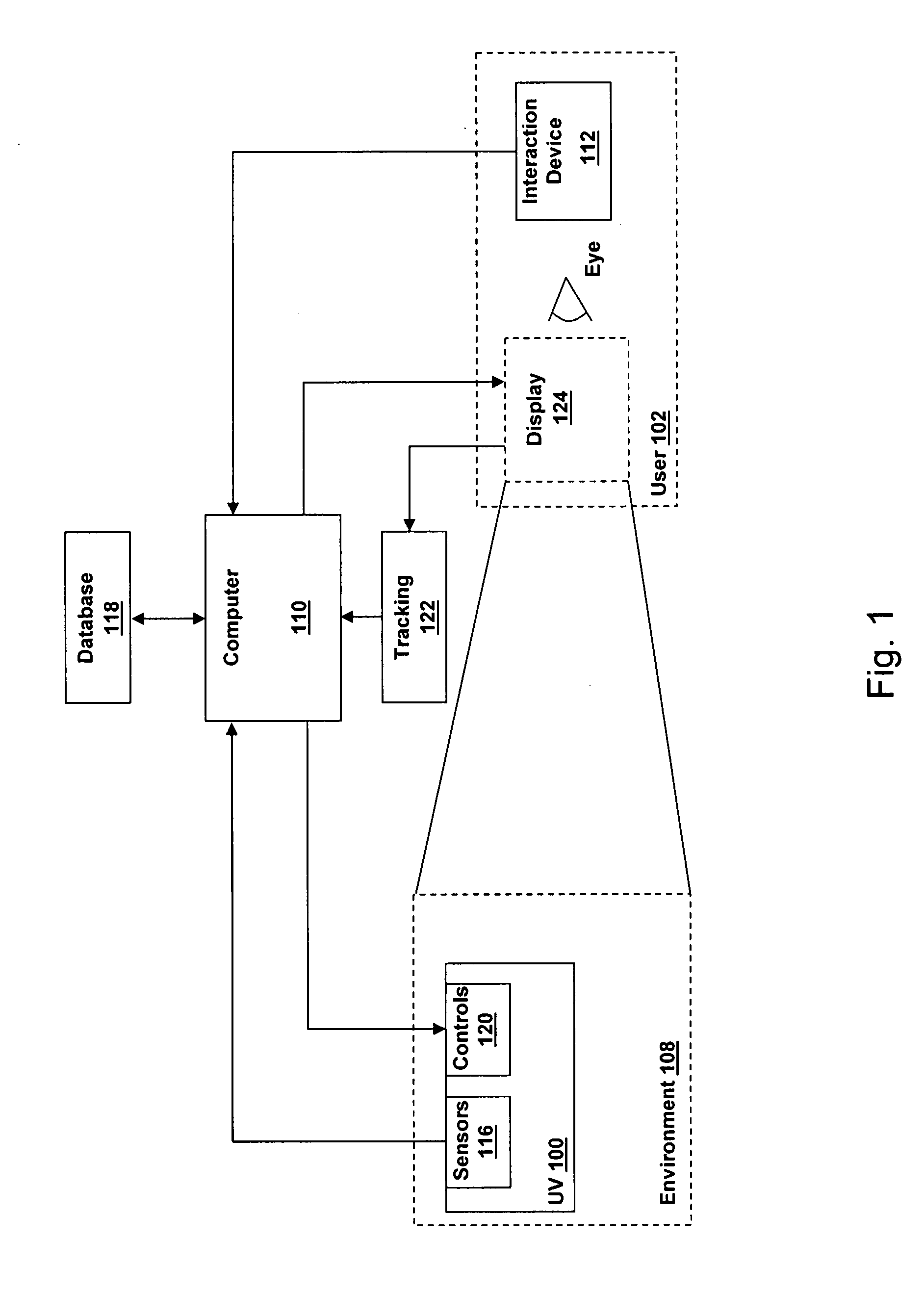
[0015]FIG. 1: Exemplary UV information and control system;

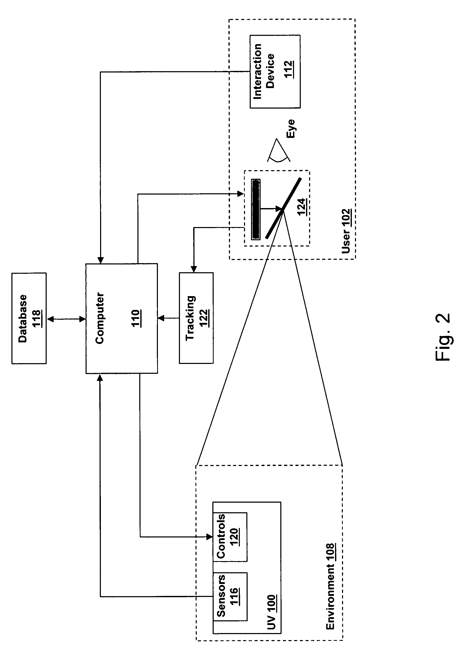
[0016]FIG. 2: Exemplary UV information and control system using an optical see-through display;

[0017]FIG. 3: Exemplary UV information and control system using a video see-through display;

[0018]FIG. 4: Exemplary UV information and control system using a camera and video display potentially at different locations;

[0019]FIG. 5: Exemplary view of information superimposed on top of a view of an environment with exemplary UV identification and control information;

[0020]FIG. 6: Exemplary view of information superimposed on top of a view of an environment with exemplary UV identification and control information;

[0021]FIG. 7: Exemplary view of information superimposed on top of a view of an environment with exemplary UV identification and control in...


PUM


Abstract

An augmented reality system identifies and controls a vehicle located within an environment. A tracking system obtains viewpoint information corresponding to a real-time view of the environment. A processing system receives information from one or more sensors. Information includes sensor location information and status information about the vehicle. Processing system generates graphics using said sensor location information and said viewpoint information. Graphics include visual representations of said status information and controls. A display displays the generated graphics such that the graphics are superimposed on the real-time view. The graphics appear attached to the vehicle. An interaction device activates a displayed control.

Description

CROSS-REFERENCE TO RELATED APPLICATIONS[0001]The present invention is related to the following co-pending U.S. patent applications, the entire contents of each of which are incorporated herein by reference:[0002]1. U.S. application Ser. No. 11 / 441,241 entitled “System and Method to Display Maintenance and Operation Instructions of an Apparatus Using Augmented Reality,” filed May 26, 2006; and[0003]2. U.S. Application Ser. No. 11 / ______ entitled “Augmented Reality-Based System and Method to Show the Location of Personnel and Sensors Inside Occluded Structures and Provide Increased Situation Awareness” filed Mar. 8, 2007.[0004]3. U.S. Application No. 11 / 516,545 entitled “Method and System for Geo-Referencing and Visualization of Detected Contaminants,” filed Sep. 7, 2006.FIELD OF THE DISCLOSURE[0005]This relates to using augmented reality-based systems with unmanned vehicles (UV).INTRODUCTION[0006]It has long been desirable to provide a remote user with control of an unmanned vehicle ...

Claims


Application Information

Patent Timeline
Patent Type & Authority Applications(United States)
IPC IPC(8): G08G1/123G06T19/00
CPCG05D1/0027G08G5/0069G08G5/0021G05D1/0033
Inventor BAILLOT, YAHAN
Owner HARRIS CORP
Why Eureka
Try Eureka