Server apparatus and video delivery method

a server and video technology, applied in the field of server apparatus and video delivery method, can solve the problems of reduced frame rate and increased delay

Inactive Publication Date: 2007-11-29
KK TOSHIBA
View PDF35 Cites 92 Cited by
  • Summary
  • Abstract
  • Description
  • Claims
  • Application Information

AI Technical Summary

Problems solved by technology

Therefore, there is a problem that a d

Method used


Image

  • Server apparatus and video delivery method
  • Server apparatus and video delivery method
  • Server apparatus and video delivery method

Examples


first embodiment

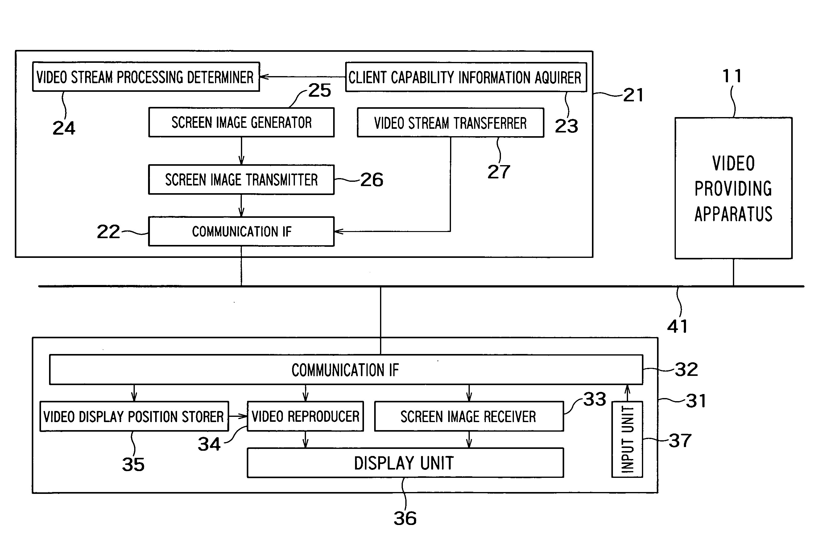
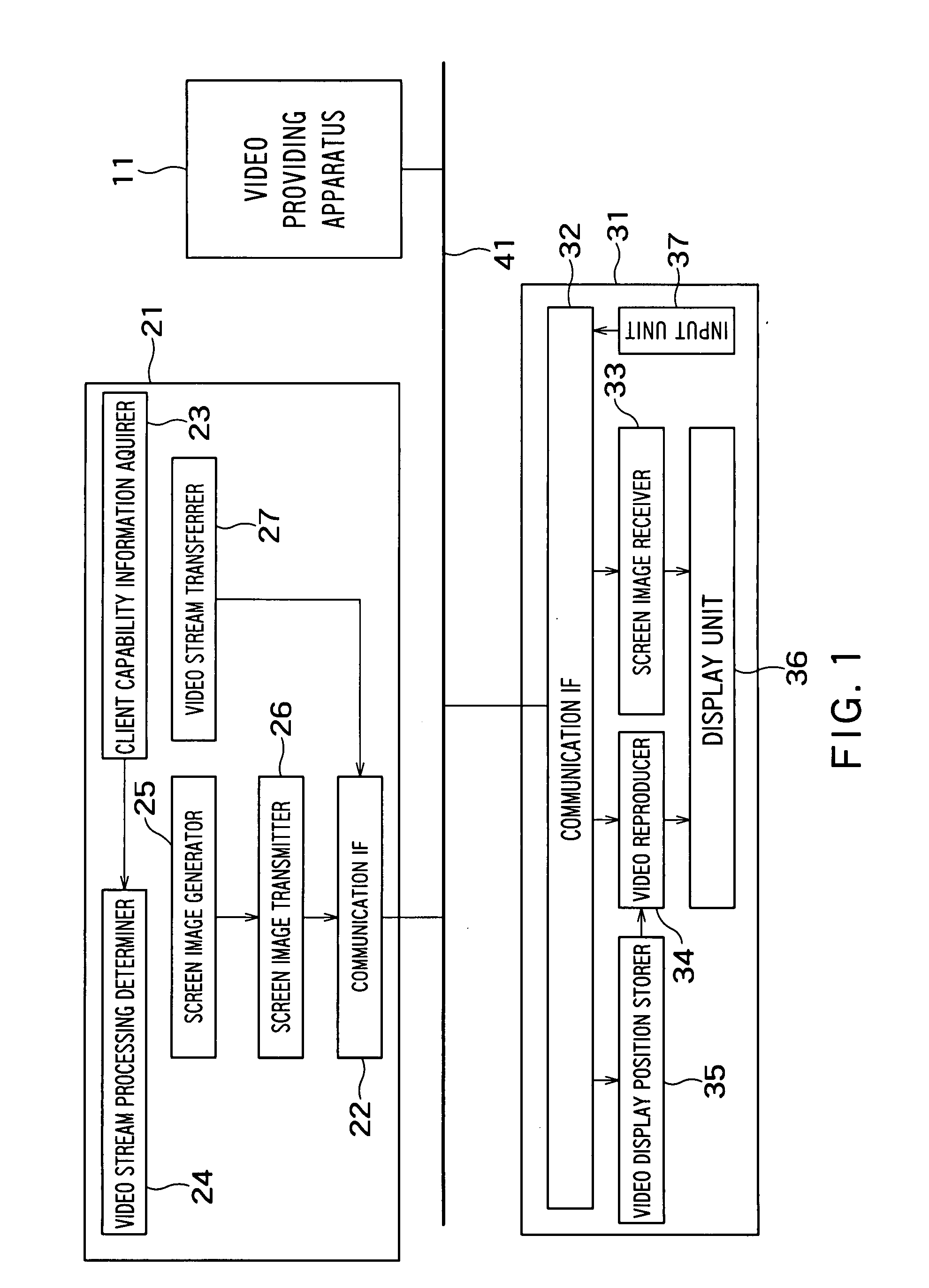
[0040]FIG. 1 is a block diagram showing a configuration of a video delivery system according to an embodiment of the present invention.

[0041]This video delivery system includes a video providing apparatus 11, a server apparatus 21 and a client apparatus 31. The video providing apparatus 11, the server apparatus 21 and the client apparatus 31 are connected to a network 41. The network 41 may be either of a wire network and a radio network.

[0042]The video providing apparatus 11 is, for example, a contents delivery server which delivers video contents, or a video phone (which may be either of a fixed phone and a mobile phone). The video providing apparatus 11 provides a video image to be displayed on the client apparatus 31, via the network 41. A video image transmitted from the video providing apparatus 11 is encoded by, for example, an arbitrary coding scheme, and transmitted as stream data. In view of the current situation, there is a possibility that the arbitrary coding scheme wil...

second embodiment

[0074]FIG. 9 is a block diagram showing a configuration of a video delivery system in a second embodiment. The second embodiment differs from the first embodiment in that a server apparatus 51 includes a video stream transmission requester 52.

[0075]FIG. 10 is a flow chart showing a processing flow in a server apparatus 51 in the second embodiment. The present embodiment differs from the first embodiment in processing conducted when the client apparatus 31 can decode the video stream provided by the video providing apparatus 11.

[0076]S21, S22, S23 and S24 are conducted in the same way as the first embodiment. S21, S22, S23 and S24 correspond to S11, S12, S13 and S14 in FIG. 7. If the client apparatus 31 can decode the above-described video format (YES at S23), the server apparatus 51 first transmits information of a position in which a video image should be displayed (a position in which a video image of the opposite party of talking should be displayed in a window of the video phone...

third embodiment

[0079]In a third embodiment, the client capability information acquirer 23 will be described in detail.

[0080]The client capability information acquirer 23 acquires capability information which represents the capability of the client apparatus 31. As for the capability of the client apparatus 31, there is, for example, a classification (such as MPEG-2, MPEG-4 or H.263) of the format of the screen image data which can be decoded by the client apparatus 31. The client capability information acquirer 23 acquires the capability information of the client apparatus 31 according to, for example, one of procedures described hereafter.

[0081]According to a first possible procedure, the client capability information acquirer 23 acquires the capability information of the client apparatus 31 from a capability information input unit provided for the user to input the identifier of the client apparatus 31 and capability information. The acquired capability information is stored in the server appara...


PUM


Abstract

There is provided with an apparatus including: a video stream receiver configured to receive a first video stream encoded by a first coding scheme from a video providing apparatus via a network; a video stream generator configured to generate a second video stream obtained by converting a coding scheme of the first video stream from the first coding scheme to a second coding scheme; a client capability information acquirer configured to acquire decoding capability information representing whether a client apparatus can decode a video image encoded by the first coding scheme; and a video stream processing determiner configured to transmit the first video stream to the client apparatus when the client apparatus can decode the video image encoded by the first coding scheme, and configured to transmit the second video stream to the client apparatus when the client apparatus cannot decode the video image encoded by the first coding scheme.

Description

CROSS-REFERENCE TO RELATED APPLICATIONS[0001]This application is based upon and claims the benefit of priority from the prior Japanese Patent Applications No. 2006-95027 filed on Mar. 30, 2006, the entire contents of which are incorporated herein by reference.BACKGROUND OF THE INVENTION[0002]1. Field of the Invention[0003]The present invention relates to a server apparatus which generates a screen image to be displayed on a client apparatus connected via a network and transmits the generated screen image to the client apparatus, and a video delivery method.[0004]2. Related Art[0005]A server apparatus which generates a screen image to be displayed on a client apparatus connected via a network and transmits the generated screen image to the client apparatus, and a client apparatus which displays the screen image received from the server apparatus on a display unit are proposed in, for example, JP-A 2002-304283 (Kokai).[0006]A client apparatus (for example, a display device) described ...

Claims


Application Information

Patent Timeline
IPC IPC(8): H04B1/66H04N7/173H04N21/222H04N21/226H04N21/2389H04N21/24H04N21/81
CPCH04N21/234309H04N21/2662H04N21/25808H04N21/234363H04N5/76
Inventor MURAI, SHINYAGOTO, MASATAKAYAMAGUCHI, KENSAKUNISHIBAYASHI, YASUYUKI
Owner KK TOSHIBA
Why Eureka
Try Eureka