Extractor device for machine tools, welding and manufacturing machines and the like

Inactive Publication Date: 2007-11-29
P E I PROTEZIONI ELABORAZIONI IND S R L FISCAL CODE 02894991203 & VAT NUMBER 02894991203
View PDF6 Cites 3 Cited by
  • Summary
  • Abstract
  • Description
  • Claims
  • Application Information

AI Technical Summary

Benefits of technology

[0008]The aim of the present invention is to produce an extractor device for machine tools, welding and manufacturing machines and the like which is free of the above-mentioned disadvantages.

Problems solved by technology

As is known, in stock removal machining processes machining waste is flung far from the area of action of the tool due to the high speed of tool rotation.
Said outlets have the disadvantage of not being able to be moved towards the machining point past a predetermined limit, both due to the shape, often irregular, of the workpiece being machined, and due to the variability of the dimensions of the various tools which may be used one after another during the machining cycle.
The direct consequence of this is inefficient shavings extraction, since the extracting action is noticeably reduced with an increase in the distance from the machining point.
However, even hoods cannot be moved towards the machining point beyond a predetermined limit, to prevent them from striking the surface being machined, above all in the cases in which said surface is very irregular.
However, in practice, it was found that both the brushes and the strips tend to wear or deform easily, compromising the efficiency of the extractor device on which they are mounted.
This means that they need substituting periodically, involving costs both for materials and labor.
Very similar and equivalent problems are also found for other manufacturing or welding machines, for example for extracting and removing from the welding area any fumes and vapors produced by welding.

Method used


Image

  • Extractor device for machine tools, welding and manufacturing machines and the like
  • Extractor device for machine tools, welding and manufacturing machines and the like
  • Extractor device for machine tools, welding and manufacturing machines and the like

Examples


Embodiment Construction

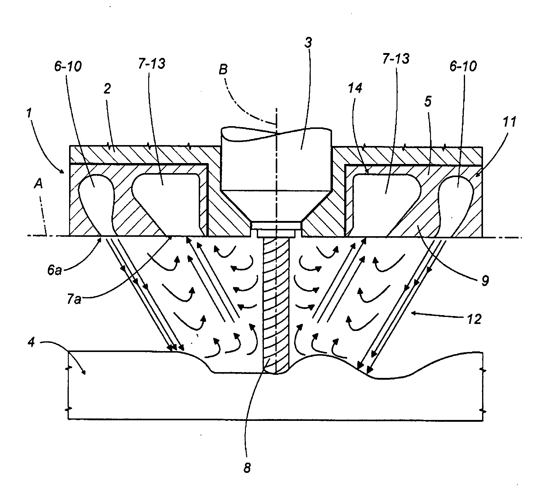
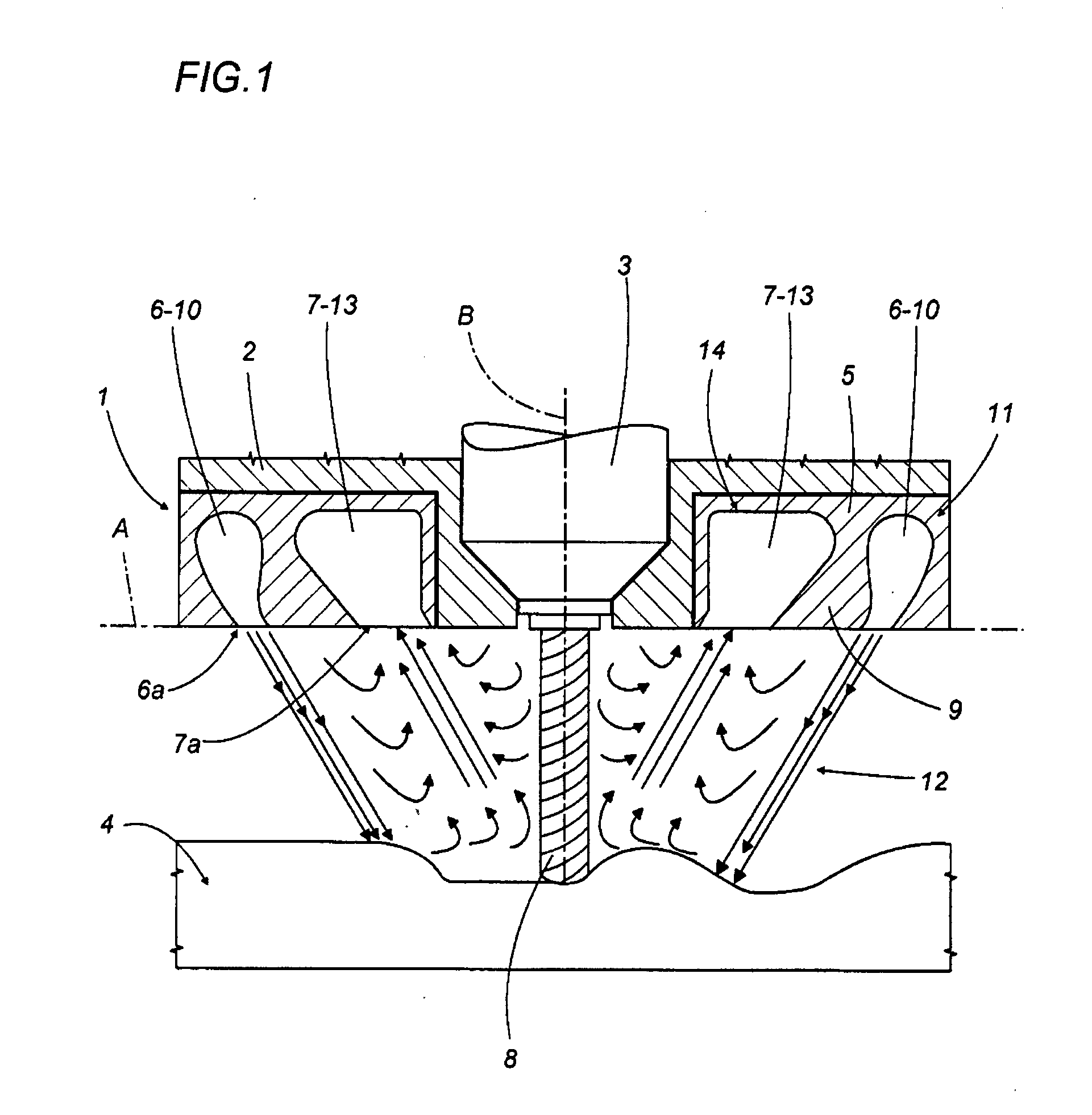
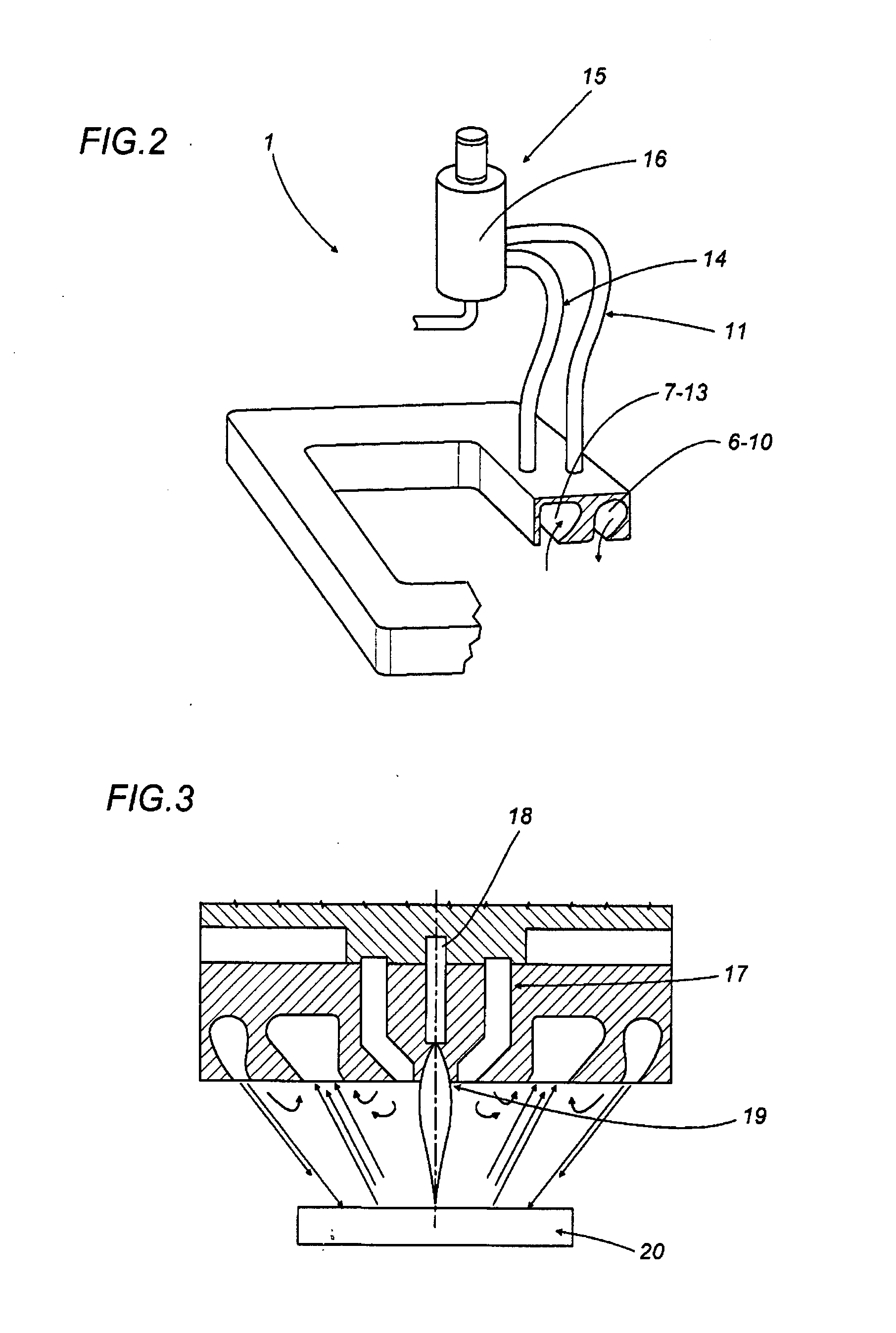
[0014]In FIGS. 1 and 2 the numeral 1 denotes as a whole an extractor device for machine tools. In particular, FIG. 1 shows the device 1 mounted, using an annular supporting flange 2, on a tool—holder machining head 3, designed to perform stock removal machining processes on a semi-finished product 4.

[0015]The device 1 comprises an interchangeable annular 5 body, mounted on the flange 2 and having, on the side facing the semi-finished product 4, two annular cavities 6 and 7, coaxial with one another, having the shape of a groove and substantially coplanar, that is to say, having respective annular openings 6a and 7a lying in the same plane A.

[0016]The plane A is at a right angle to the axis of rotation B of the tool 8 mounted on the machining head 3. The axis B is also the central axis about which the openings 6a and 7a extend concentrically and is also, according to at least one plane at a right angle to the plane A, an axis of symmetry for the body 5 and, in particular, for the cav...


PUM

PropertyMeasurementUnit
Symmetryaaaaaaaaaa
Perimeteraaaaaaaaaa

Abstract

An extractor device for machine tools which have at least one tool - holder machining head has an annular blowing distributor for generating a tubular gaseous barrier around the tool—holder machining head, and an annular extractor manifold, positioned inside the barrier and concentric with the annular blowing distributor, for extracting shavings and / or dusts created by machining confined in the barrier.

Description

BACKGROUND OF THE INVENTION[0001]The present invention relates to an extractor device for machine tools, welding and manufacturing machines and the like.[0002]In particular, the present invention relates to an extractor device designed to be installed on the machining heads of machine tools to remove shavings and dusts from the machining area, or, for example, on welding torches for removing and extracting the fumes and vapors from the welding area, without in any way limiting the scope of the invention.[0003]As is known, in stock removal machining processes machining waste is flung far from the area of action of the tool due to the high speed of tool rotation.[0004]A known solution for keeping the machining area and the surrounding area clean is to convey and collect shavings and dusts in special channels by means of extractor outlets positioned close to the tools which perform the machining. Said outlets have the disadvantage of not being able to be moved towards the machining poi...

Claims


Application Information

Patent Timeline
IPC IPC(8): B23Q11/00
CPCB23Q11/0046Y10T408/50Y10T409/304088B23Q11/0858
Inventor BENEDETTI, MICHELETABELLINI, GIORGIO
Owner P E I PROTEZIONI ELABORAZIONI IND S R L FISCAL CODE 02894991203 & VAT NUMBER 02894991203
Why Eureka
Try Eureka