Tool holder arrangement

a tool and holder technology, applied in the direction of metal tool holders, supports, positioning apparatuses, etc., can solve the problems that contact cannot provide a ground path, and conventional identification means such as labeling or marking cannot be used to distinguish tools

Active Publication Date: 2006-03-07
PROSURGICS
View PDF9 Cites 51 Cited by
  • Summary
  • Abstract
  • Description
  • Claims
  • Application Information

AI Technical Summary

Benefits of technology

[0027]In order that the present invention may be more readily understood, embodiments thereof will now be described, by way of example, with reference to th...

Problems solved by technology

Because the tools must be sterile to qualify for use in surgical procedures, conventional identification means such as labeling or marking may not be available for the purpose of distinguish...

Method used


Image

  • Tool holder arrangement
  • Tool holder arrangement

Examples


Embodiment Construction

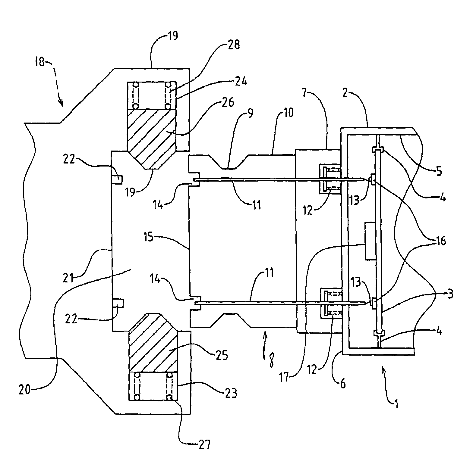
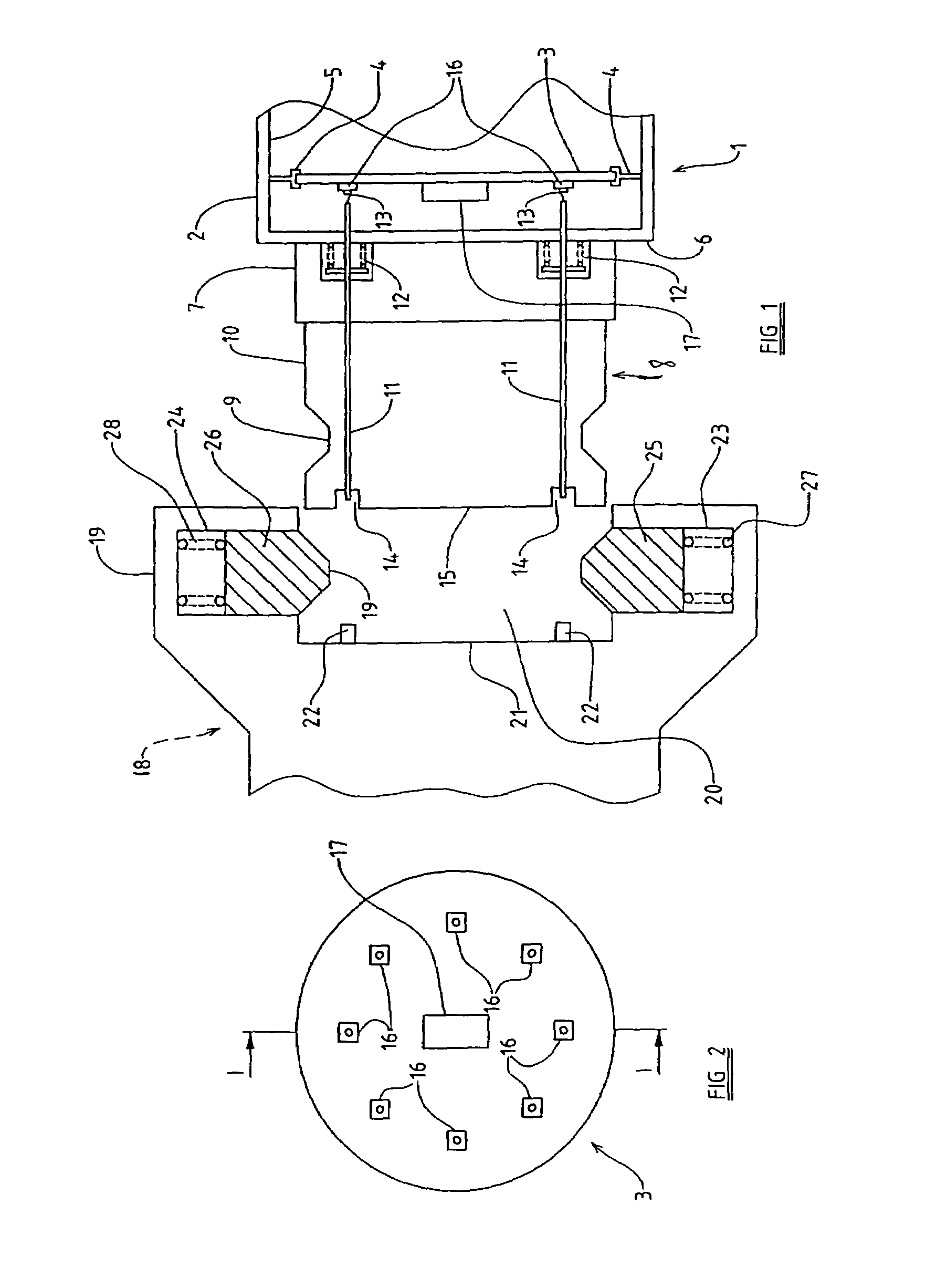
[0030]Referring to FIG. 1, a tool-receiving end 1 of the arm of a medical robot is shown. The tool-receiving end comprises a housing 2, which is substantially circular in cross section. A substantially circular printed circuit board (PCB) 3 is provided within the housing, the PCB 3 being of slightly smaller radius than the housing 2, and being arranged to be coaxial therewith. The PCB 3 is held in place by suitable mounts 4, which are each attached to an interior surface 5 of the housing 2.

[0031]Supported on a front surface 6 of the housing 2 is a substantially cylindrical insulating block 7, which is formed from a substantially electrically non-conducting material. The insulating block 7 is also arranged to be substantially coaxial with the tool-receiving end 1. Mounted on the insulating block 7, on the opposite side thereof from the tool-receiving end 1, is a connector 8, which is substantially cylindrical (and again coaxial with the tool-receiving end 1), but which has a groove 9...


PUM


Abstract

A tool identification system has a tool holder allowing removable attachment thereto of any one of a plurality of tools; a sensor arrangement operable to sense features present on a tool attached to the tool holder; a processor operable to identify uniquely, from the sensed features, the type of the tool attached to the tool holder; and an insulation arrangement provided between the tool holder and the sensor arrangement, thereby electrically insulating the tool holder from the sensor arrangement.

Description

RELATED U.S. APPLICATIONS[0001]Not applicable.STATEMENT REGARDING FEDERALLY SPONSORED RESEARCH OR DEVELOPMENT[0002]Not applicable.REFERENCE TO MICROFICHE APPENDIX[0003]Not applicable.FIELD OF THE INVENTION[0004]This invention relates to a tool holder arrangement, and in particular concerns a tool holder arrangement incorporating a system for uniquely identifying a surgical tool attached to a tool holder.BACKGROUND OF THE INVENTION[0005]The use of medical robots has become widespread in recent years, in particular for surgical procedures requiring a high degree of precision, for instance minimal access or “keyhole” surgery.[0006]Typically, a medical robot comprises an arm which is movable under computer control, and to which any one of several different tools may be attached. During the course of a surgical procedure, several different tools may be required, and each will be attached in turn to the arm of the medical robot.[0007]Because the tools must be sterile to qualify for use in...

Claims


Application Information

Patent Timeline
IPC IPC(8): B23Q3/155A61B17/00A61B19/00
CPCA61B19/26B23Q3/15546A61B19/2203A61B2017/00482Y10T483/134Y10S483/901Y10T483/14A61B2019/448A61B90/50A61B34/30A61B90/98
Inventor FITZGIBBON, RUSSELL PATRICK
Owner PROSURGICS
Why Eureka
Try Eureka