Toolhead for multi-axis machine tools

a multi-axis machine tool and tool head technology, applied in the direction of attachable milling devices, manufacturing tools, transportation and packaging, etc., can solve the problems of slowing down operations, affecting production efficiency, and affecting the operation of the toolhead,

Active Publication Date: 2007-05-22
JOBS SPA
View PDF12 Cites 54 Cited by
  • Summary
  • Abstract
  • Description
  • Claims
  • Application Information

AI Technical Summary

Benefits of technology

[0012]In particular, the object of the invention is to set forth a toolhead for multi-axis machine tools such as will perform depth-controlled machining operations on surfaces located at whatever height relative to the feed direction of the tool.
[0106]In addition, the toolhead disclosed will allow machining at controlled depth using tool-holders of standard design which are more economical, smaller and lighter, and more easily obtainable than those utilized typically hitherto for applications of the type in question.
[0107]The toolhead according to the present invention allows rapid and fully automatic replacement of the tool-holder, without any part of the head or the machine needing to be removed. In particular, there is no need to dismantle the dust extraction port.
[0108]Again, given that the depth stop element of a toolhead according to the invention is not mounted to the tool-holder by way of shielded bearings, the speed of rotation of the spindle is not limited.
[0016]The toolhead further comprises a depth stop element, affording an active surface substantially transverse to the machining axis and positionable against the surface of a workpiece, mounted to the support assembly and capable of movement along the machining axis between an extended first position, distanced from the spindle, and a retracted second position of proximity to the spindle, also sensing means able to identify the position of the active surface relative to the support assembly and thus monitor the depth to which the tool penetrates the workpiece.
[0110]The above noted advantages translate into minimal down times between work cycles, and consequently optimized production.

Problems solved by technology

Disadvantageously, devices of the prior art type noted above are integrated into the tool-holder mounted to the spindle of a toolhead.
The applicant finds that prior art devices as outlined above are improvable in a number of ways.
A machine therefore has to be equipped with a plurality of tool-holders, each incorporating the depth-control device, which in comparison to standard tool-holders are much more expensive, and much heavier.
Moreover, given that the sensor serving to detect the displacement of the stop cage device in prior art embodiments is installed on the toolhead, near to the spindle, the setting of the sensor needs to be checked after every tool change, and this has the effect of slowing down operations even if the check is run automatically.
Also, the bearings coupling the stop cage to the tool-holder operate in a dust-laden environment and must therefore be shielded; consequently, spindle speeds must not exceed 16000 rev / min or thereabouts otherwise these components could overheat.

Method used


Image

  • Toolhead for multi-axis machine tools
  • Toolhead for multi-axis machine tools
  • Toolhead for multi-axis machine tools

Examples


Embodiment Construction

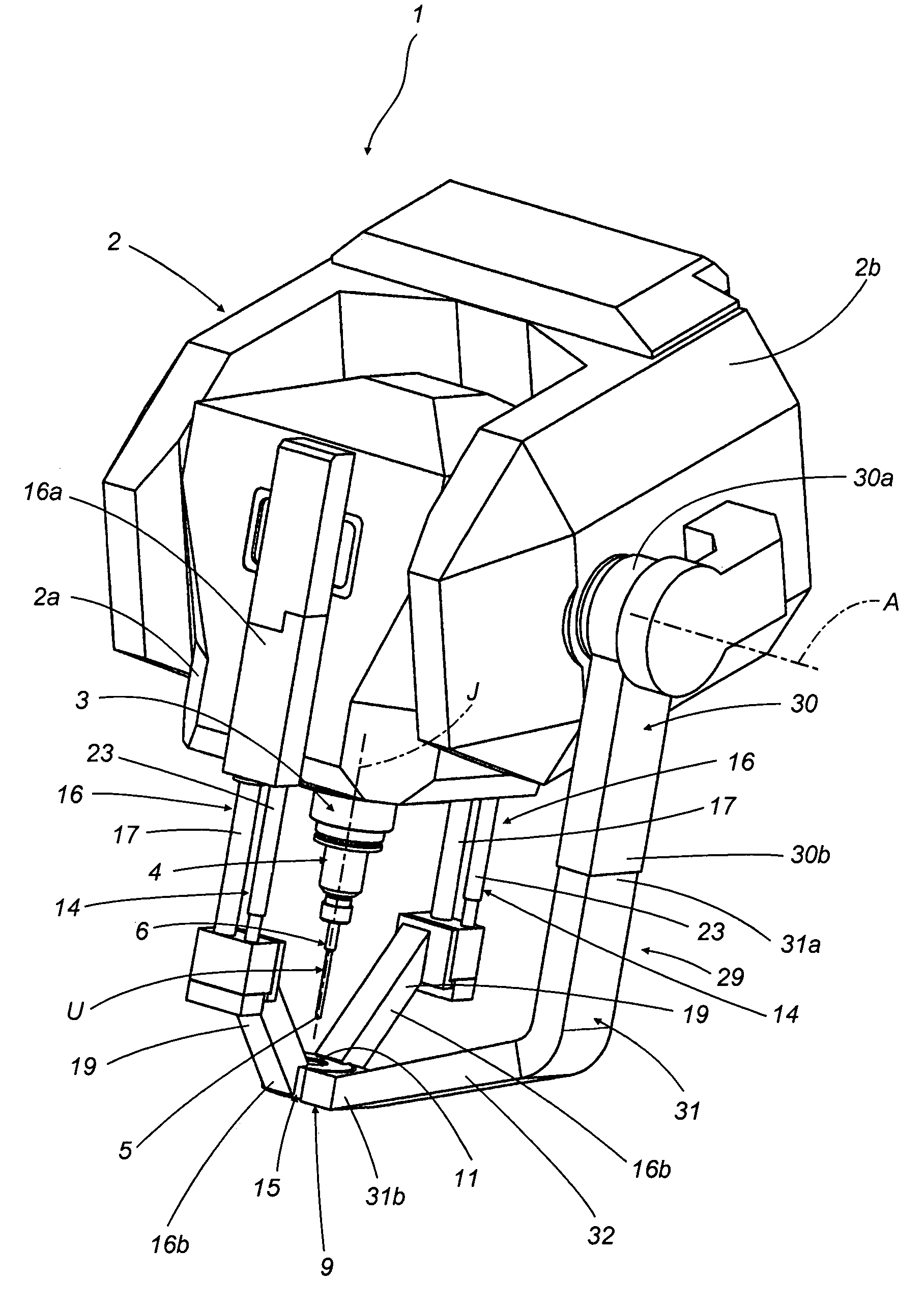
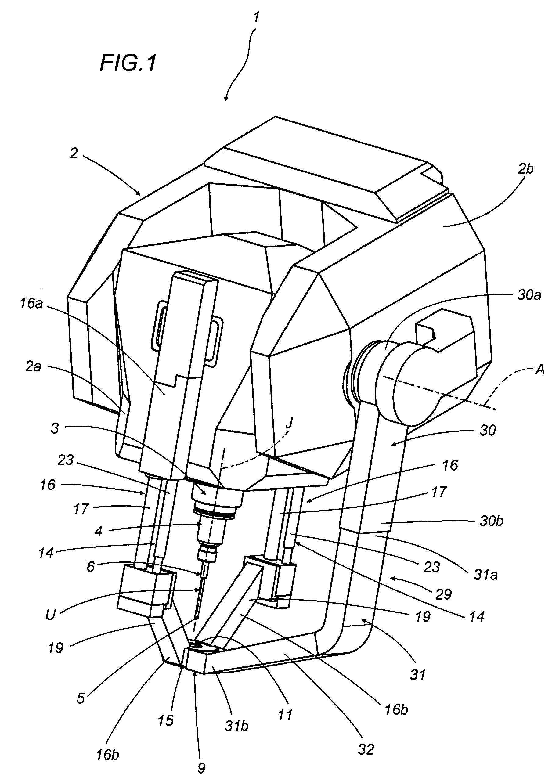
[0026]Referring to the drawings, 1 denotes a toolhead for multi-axis machine tools, in its entirety.

[0027]The toolhead 1 will be mounted generally to a numerically controlled multi-axis machine tool of conventional type, which is neither described in detail herein nor illustrated in the drawings.

[0028]The machine tool typically comprises a bed on which the toolhead 1 is mounted with freedom of movement, relative to the bed, along a plurality of positioning axes. The toolhead 1 is positioned on the various axes by drive means interlocked to a processing and control unit and serving also to govern the rotation of a tool about a respective machining axis on the basis of data programmed into the selfsame control unit.

[0029]The toolhead 1 comprises an assembly 2 designed to support a spindle 3 and, mounted to the spindle, a removable tool-holder 4 preferably of standard type, that is to say a given model or pattern regarded as universal and in widespread use within the art field concerne...


PUM

PropertyMeasurementUnit
distanceaaaaaaaaaa
depthaaaaaaaaaa
heightaaaaaaaaaa

Abstract

A toolhead for use on a multi-axis machine tool consists of a support assembly equipped with a pivoting spindle designed to accept a removable tool-holder, and centered on a machining axis about which a tool clamped to the tool-holder can be driven in rotation. Also forming part of the toolhead is a depth stop affording an active surface substantially transverse to the machining axis and positionable against a surface of a workpiece. The depth stop is mounted to the support assembly and capable of movement along the machining axis between a first position, distanced from the spindle, and a second position of proximity to the spindle. Transducers incorporated into the toolhead are able to sense the position of the active surface relative to the support assembly, and thus used to control the depth to which the workpiece is penetrated by the tool.

Description

BACKGROUND OF THE INVENTION[0001]The present invention relates to a toolhead for multi-axis machine tools.[0002]A toolhead embodied according to the invention is able to perform drilling, countersinking or other machining operations automatically and to extremely close tolerances, given an approximate knowledge of the surface being machined. In particular, the toolhead disclosed will countersink to a controlled depth on surfaces lying at any height relative to the feed direction of the tool.[0003]The invention can be associated to advantage with numerically controlled multi-axis machine tools as used especially in the aircraft-building industry for drilling and countersinking holes in the outer panels of wing structures and fuselage sections, destined to accommodate rivets. In practice, the heads of the inserted rivets must remain perfectly flush with the outer skin of the aircraft in order to ensure they will not generate turbulence, which would occasion a marked increase in aerody...

Claims


Application Information

Patent Timeline
Patent Type & Authority Patents(United States)
IPC IPC(8): B23B39/00B23B35/00B23C9/00B23B49/00B23Q11/00B23Q17/22
CPCB23Q11/0046B23Q17/2233B23B2215/04Y10T408/5623Y10T409/30392Y10T409/309352Y10T408/46Y10T408/56245Y10T409/304088Y10T409/30784Y10T409/308232Y10T408/50
Inventor FERRARIFOLETTI, SANDRO
Owner JOBS SPA
Why Eureka
Try Eureka