Removable Stent

Active Publication Date: 2007-11-29
MERIT MEDICAL SYST INC
View PDF28 Cites 20 Cited by
  • Summary
  • Abstract
  • Description
  • Claims
  • Application Information

AI Technical Summary

Benefits of technology

[0016] The connectors extend out from the ridge area of two struts of an annular segment between two struts of the adjacent annul

Problems solved by technology

However, the vascular walls can be traumatized

Method used


Image

  • Removable Stent
  • Removable Stent

Examples


Embodiment Construction

[0005] The invention solves this problem in a stent in accordance with the features of protective claim 1.

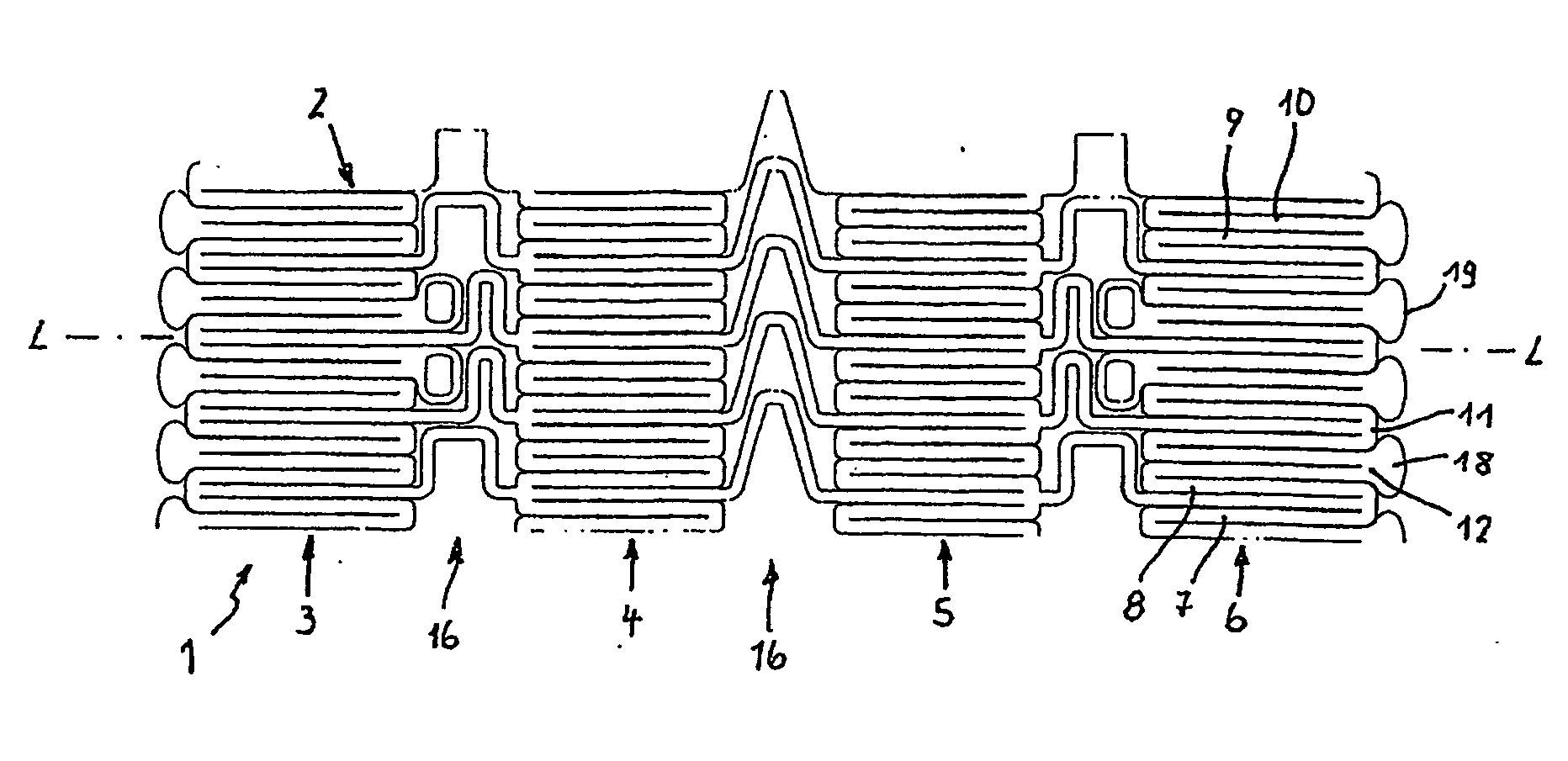
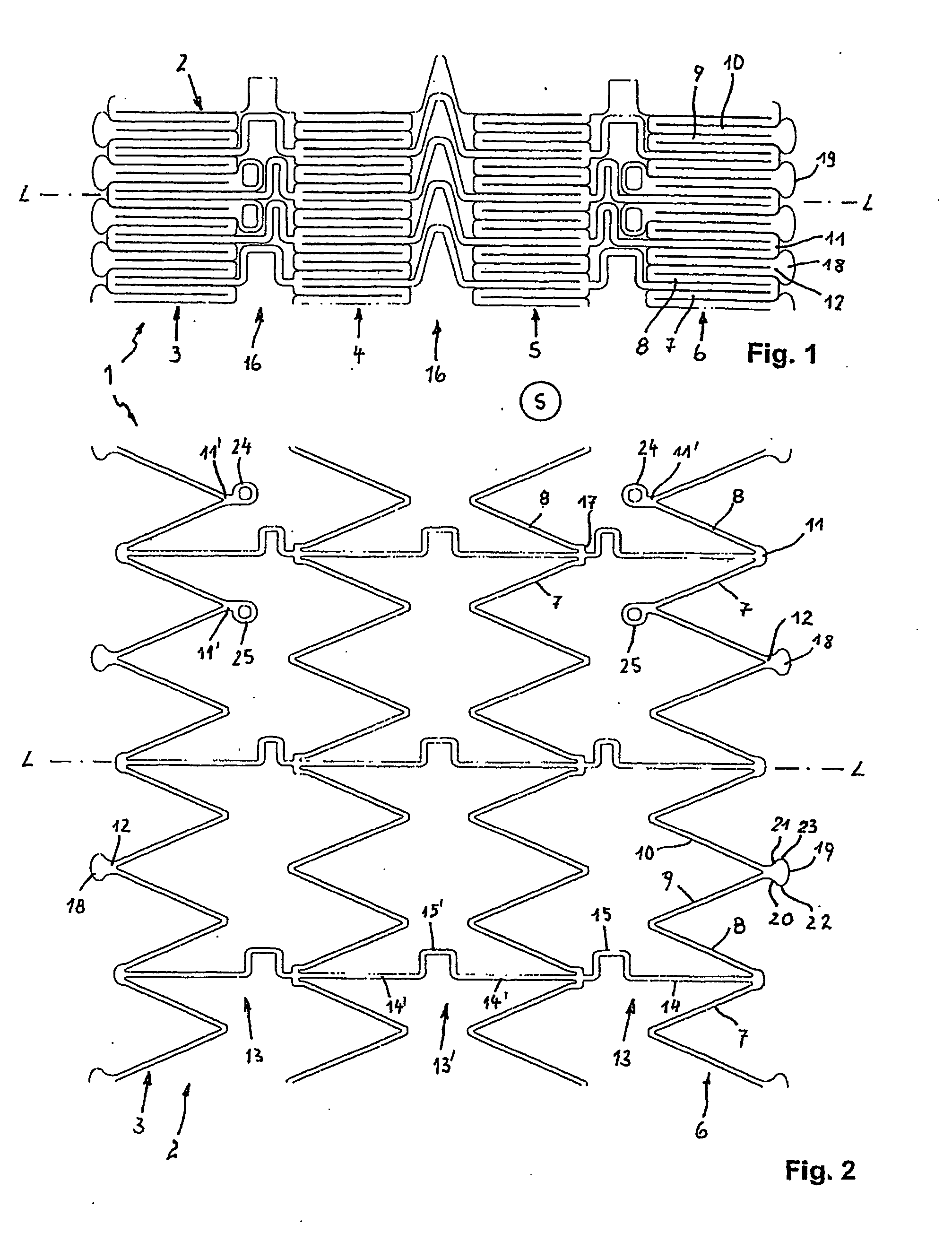
[0006] According to this claim the support frame consists of at least two annular segments formed by struts that endlessly follow each other in a corrugated manner via transitional sections. Adjacent annular segments are coupled by connectors. Every second front transitional section on the end-side annular segments, viewed in the direction of the longitudinal axis of the stent, has a widened head end that projects axially opposite the adjacent transitional sections and has a convexly rounded front section and concavely rounded throat sections between the head end and the struts connected to the head end.

[0007] According to the invention the head ends are optimized by being rounded off in order to improve their atraumatic function. The rounded head ends assure a protective contact of the front ends of the stent on the vascular wall. Thus, the stent in accordance with the invent...


PUM


Abstract

The invention is relative to a stent with a tubular support frame consisting of axially successively following, interconnected annular segments which support frame is surrounded on its outside by a thread. The thread ends are guided via a deflection from the outside into support frame, where they are coupled by a connector consisting of a material visible in x-rays. Deflection is realized by two deflection elements in the form of eyelets provided on annular segments. Deflection elements are arranged on the circumference of support frame at an interval from one another and are provided on end-side annular segments, viewed in longitudinal direction of the stent.

Description

FIELD OF INVENTION [0001] The invention is relative to a stent with suture mediated removability features. BACKGROUND OF THE INVENTION [0002] Stents are used for the permanent or also only temporary splinting of body canals that are closed or constricted as a consequence of a stenosis. [0003] Stents are introduced by catheter techniques and similar introductory aides into the intracorporal vessel in the area of the stenosis, where they function as vascular prosthesis for supporting the inner vascular walls. However, the vascular walls can be traumatized during the placing and the removal of stents. A stent can also traumatize the vessels in its placed state on account of its intrinsic movement. [0004] The invention is therefore based on the problem of creating a stent that is improved as regards compatibility with the vessels and in the case of which the danger of injuring the vascular walls during placing or removal is reduced. SUMMARY OF EXEMPLARY EMBODIMENTS [0005] The invention ...

Claims


Application Information

Patent Timeline
IPC IPC(8): A61F2/06A61FA61F2/00A61F2/90
CPCA61F2/91A61F2/915A61F2002/91516A61F2002/91533A61F2230/0054A61F2002/91575A61F2002/9528A61F2250/0059A61F2002/91566
Inventor NISSL, THOMASMANGIARDI, ERIC K.
Owner MERIT MEDICAL SYST INC
Why Eureka
Try Eureka