
Table Substitution

a table and data technology, applied in the field of data systems, can solve the problems of inability to access existing data, proprietary software applications, and not providing interfaces that enable other applications, and achieve the effect of avoiding the need for data exchange, facilitating data exchange between applications, and facilitating data exchang

Active Publication Date: 2007-11-29
ORACLE INT CORP
View PDF12 Cites 79 Cited by
  • Summary
  • Abstract
  • Description
  • Claims
  • Application Information

AI Technical Summary

Problems solved by technology

Oftentimes, such software applications are proprietary and do not provide interfaces that enable other applications to access data stored by the applications.
Generally, these data formats and architectures correspond to different data models that are defined in a manner that makes it impractical or impossible to share data between applications.
This becomes particularly problematic for those enterprises that have been using a certain application or application systems for years, such as a manufacturing processing tool or a large customer database application, and have a great deal of data that has been generated through use of the tool or application and stored in a large data store: the new improved tool or application cannot access the existing data in a reliable or useful manner, and years or even decades of information must be re-entered into the new system.
In general, this is a burdensome task, both in developing the special business logic and administrating the replication process.
It also adds overhead to each database, as large imports and exports are very transaction intensive.
Furthermore, in reality the databases are never fully synchronized, since each export represents a “snapshot” of the data in each table at the time that data is retrieved by the export tool, which will have changed by the time the replication process is completed.

Method used


Image

  • Table Substitution
  • Table Substitution
  • Table Substitution

Examples


Embodiment Construction

[0023] A system and method for “substituting” tables is described in detail herein. In the following description, numerous specific details are disclosed to provide a thorough understanding of embodiments of the invention. One skilled in the relevant art will recognize, however, that the invention can be practiced without one or more of the specific details, or with other methods, components, etc. In other instances, well-known structures or operations are not shown or described in detail to avoid obscuring aspects of various embodiments of the invention.

[0024] Reference throughout this specification to “one embodiment” or “an embodiment” means that a particular feature, structure, or characteristic described in connection with the embodiment is included in at least one embodiment of the present invention. Thus, the appearances of the phrases “in one embodiment” or “in an embodiment” in various places throughout this specification are not necessarily all referring to the same embod...


PUM


Abstract

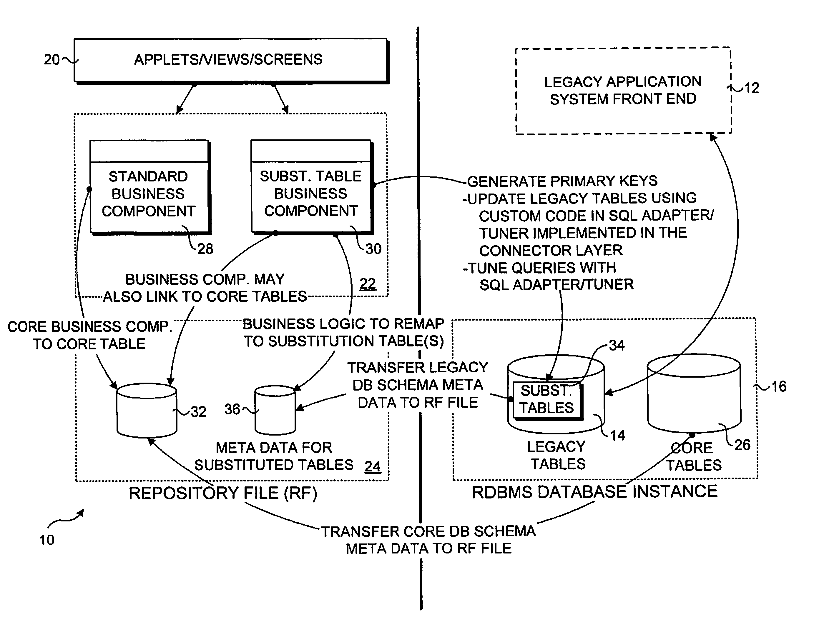
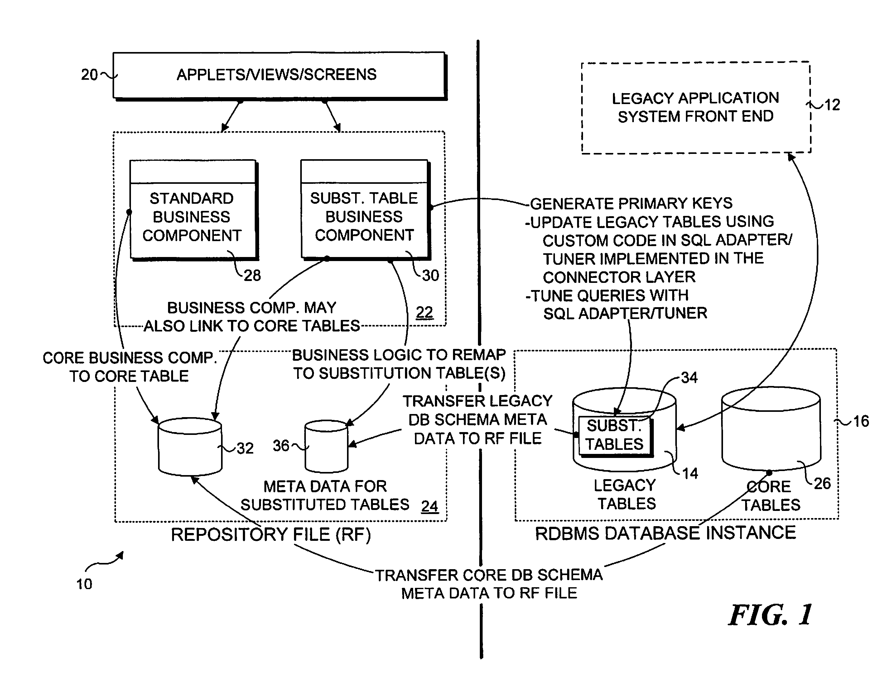
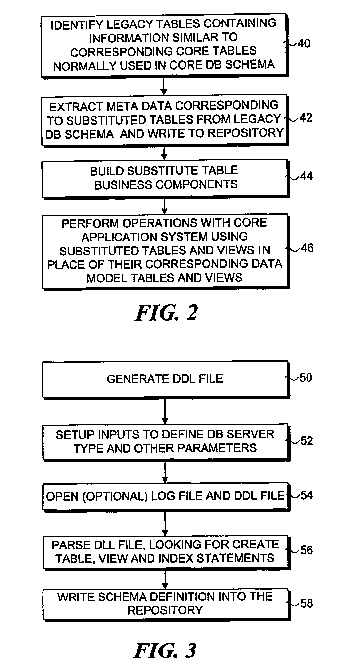
A method and system that enables data to be shared across application systems via a table substitution scheme. Tables are identified in the legacy application system that are candidates for substitution of tables in the core application system containing similar data. Table structure meta data corresponding to these “substituted” tables are then extracted from the legacy system schema, and stored in a repository. In accordance with the meta data, business logic is defined to remap columns in the core tables to corresponding columns in the substituted tables. Accordingly, when the core application system performs data access (e.g., reads, inserts, updates, etc.), it accesses the remapped columns in the substituted tables instead of original columns in the core tables. At the same time, the legacy application system is enabled to concurrently access the substituted tables without require any changes to the business logic of the legacy application system.

Description

RELATED APPLICATIONS [0001] This application is a divisional of U.S. patent application Ser. No. 10 / 234,417, which is now U.S. Pat. No. 7,257,597, entitled “Table Substitution,” filed on Sep. 3, 2002, and naming Alex Pryce, Jeffrey Boyd and Scott Kurinskas as inventors, which is based on a U.S. Provisional Application No. 60 / 342,058, entitled “Table Substitution,” filed on Dec. 18, 2001. These applications are incorporated by reference herein, in their entirety and for all purposes.BACKGROUND OF THE INVENTION [0002] 1. Field of the Invention [0003] The present invention relates to data systems in general, and, in more particular, a mechanism for substituting tables such that two separate enterprise applications may access the same tables using a common database instance. [0004] 2. Background Information [0005] There are many instances in which corporate enterprises spend a large amount of resources supporting a particular software application or suite of applications. Oftentimes, su...

Claims


Application Information

Patent Timeline
Patent Type & Authority Applications(United States)
IPC IPC(8): G06F17/00
CPCY10S707/99943G06F17/30557G06F17/303Y10S707/99942G06F16/25G06F16/214
Inventor PRYCE, ALEXBOYD, JEFFREYKURINSKAS, SCOTT
Owner ORACLE INT CORP
Learn More