System and method for filling containers

a technology of system and container, applied in the field of system and method for filling containers, can solve the problems of significant waste and require a separate cleaning step, and achieve the effect of eliminating waste and more controlled fluid transfer

Active Publication Date: 2007-12-06
ADVANCED SCIENTIFICS INC
View PDF11 Cites 12 Cited by
  • Summary
  • Abstract
  • Description
  • Claims
  • Application Information

AI Technical Summary

Benefits of technology

[0014]From the present disclosure, it will be appreciated by one with ordinary skill in the art that the present invention provides a number of advantages over the prior art, including, for example, that close cooperation between the nozzle mechanism and connector advantageously allows for a more controlled transfer of fluid to the container, w

Problems solved by technology

Unfortunately, these systems suffer from a number of disadvantages with regard to maintaining the controlled environment within the transfer conduit while accomplishing the transfer as quickly and efficiently as possible.
Still other such syst

Method used


Image

  • System and method for filling containers
  • System and method for filling containers
  • System and method for filling containers

Examples


second embodiment

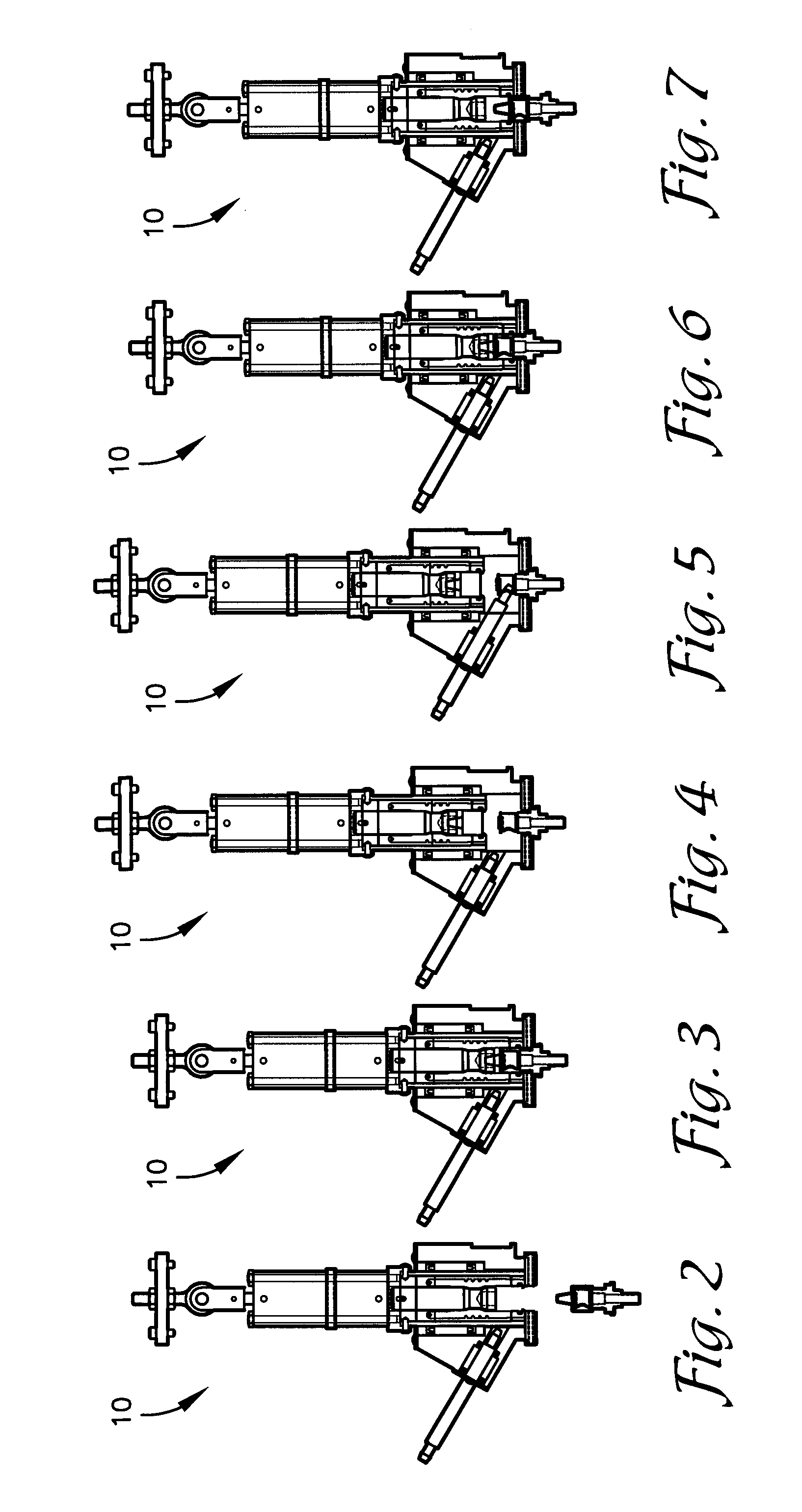
[0028]FIG. 12 is a sectional elevation view of the system of the present invention shown in a first stage of operation;

[0029]FIG. 13 is a sectional elevation view of the system of FIG. 12 shown in a second stage of operation;

[0030]FIG. 14 is a sectional elevation view of the system of FIG. 12 shown in a third stage of operation;

[0031]FIG. 15 is a sectional elevation view of the system of FIG. 12 shown in a fourth stage of operation;

[0032]FIG. 16 is a sectional elevation view of the system of FIG. 12 shown in a fifth stage of operation; and

[0033]FIG. 17 is a sectional elevation view of the system of FIG. 12 shown in a sixth stage of operation.

DETAILED DESCRIPTION OF THE INVENTION

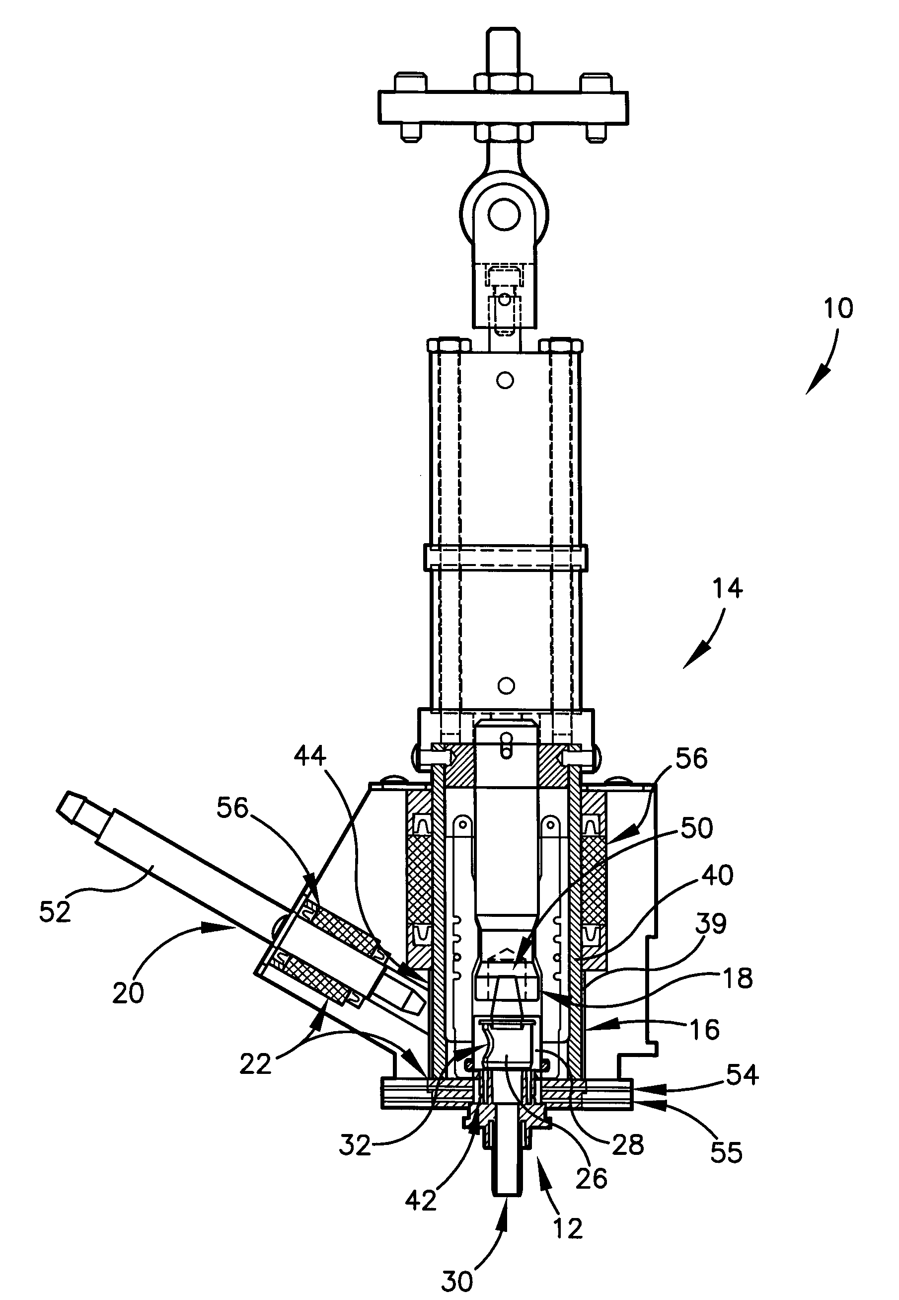
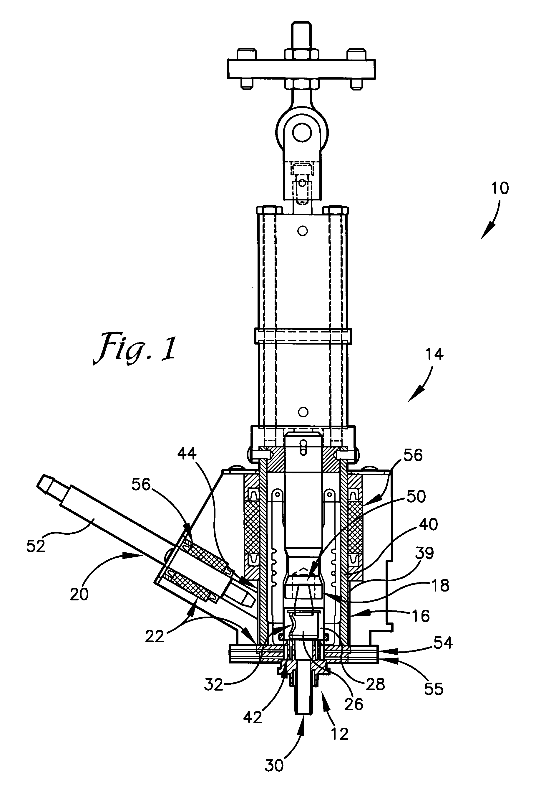
[0034]With reference to the drawing figures, a system and method is described, shown, and other disclosed herein in accordance with one or more preferred embodiments of the present invention. Broadly, the system and method allow for substantially automatically aseptically or non-aseptically filling a containe...

first embodiment

[0058]From the foregoing discussion, it will be appreciated by one with ordinary skill in the art that the present invention provides a number of advantages over the prior art, including, for example, that close cooperation between the nozzle mechanism and connector allows for a more controlled transfer of fluid to the container, which eliminates waste and the need for a separate cleaning step prior to completion. Furthermore, in the first embodiment, the connector and filling chamber are sterilized at the beginning of every fill cycle, there is a complete sterilization rinse cycle after a pre-set number of fills, and measurable and measured sterilization of all moving components is allowed for. For these and other reasons, the present invention allows for more quickly and efficiently filling containers.


PUM

PropertyMeasurementUnit
Angleaaaaaaaaaa
Angleaaaaaaaaaa
Angleaaaaaaaaaa

Abstract

A system (10) and method for substantially automatically aseptically or non-aseptically filling a container with a fluid. The transfer of fluid occurs via a movable nozzle mechanism (20) substantially automatically inserted into a side opening (32) in a connector (12) attached to the container. More specifically, the side opening (32) in the connector (12) is exposed, the nozzle mechanism (20) is moved into the side opening (32), the fluid is transferred into the container via the nozzle mechanism (20) and the connector (12), the nozzle mechanism (20) is removed from the side opening (32) in the connector (12), and the side opening (32) in the connector (12) is closed. The aseptic transfer of fluid includes a substantially automatic sterilization procedure accomplished by both spray and contact components (54,56).

Description

RELATED APPLICATIONS[0001]The present U.S. non-provisional patent application is related to and claims priority benefit of an earlier-filed U.S. provisional patent application of the same title, Ser. No. 60 / 803,403, filed May 30, 2006. The identified earlier-filed provisional application is incorporated by reference herein.BACKGROUND OF THE INVENTION[0002]1. Field of the Invention[0003]The present invention relates broadly to systems and methods for filling containers. More specifically, the present invention concerns a system and method for substantially automatically aseptically or non-aseptically filling a container with a fluid, wherein the transfer of fluid occurs via a movable nozzle mechanism substantially automatically inserted into a side opening in a connector attached to the container, and wherein the aseptic transfer of fluid includes a substantially automatic sterilization procedure.[0004]2. Background of the Invention[0005]It is often desirable to quickly and efficient...

Claims


Application Information

Patent Timeline
IPC IPC(8): B65B39/00F16K51/00
CPCB65B55/10B65B39/004Y10T137/4245
Inventor MARTIN, CARL
Owner ADVANCED SCIENTIFICS INC
Why Eureka
Try Eureka