Al technical title is built by PatSnap Al team. It summarizes the technical point description of the patent document.
a technology for heating food and appliances, applied in lighting and heating equipment, ovens, ovens, etc., can solve problems such as inability to meet customer requirements, product temperature may drop, and product heat loss
Inactive Publication Date: 2007-12-06
PHASE CHANGE ENERGY SOLUTIONS INC
View PDF11 Cites 41 Cited by
Summary
Abstract
Description
Claims
Application Information
AI Technical Summary
This helps you quickly interpret patents by identifying the three key elements:
Problems solved by technology
Method used
Benefits of technology
[0114] The electrical resistance heating of the heating grid then causes the heating grid to rise to a temperature of approximately 240° F. within approximately 2.5 minutes. A food product such as pizza or any other food item for which it is desirable to keep warm is placed in the food product receiving area 12. The food product could be hot sandwiches, pizza, casseroles or other food items. The heater is disconnected from the power source. The article such as a food product is then delivered in the delivery apparatus. The delivery step is typically carried out by placing the delivery apparatus in a vehicle such as a car or truck and driving the vehicle to the customers' home or business. An advantage of the present invention is that the delivery apparatus does not need to be plugged into a power source such as a cigarette lighter in the vehicle during transport to the customer.
[0115] It is also noted that in accordance with the embodiment shown in FIG. 6, the pizza or other food product can be placed in the delivery apparatus after more than 2.5 minutes from the beginning of the charging step. For example, a pizza bag 11 containing a wrap heater 29 may be left plugged into the power source for up to about 1.5 hours before the controller allows the pizza bag 11 to cool to room temperature. Therefore an exemplary use is to leave the bag 11 and wrap heater 29 plugged into the power source for up to about one hour and then place the pizza into the food receiving area, unplug the heater and transport the entire delivery apparatus to the customer. Alternatively, the food product may be placed in the delivery apparatus before the charging step. This alternative does not result in a cold food product because of the short amount of time (2.5 minutes) that it takes to charge the heater.
[0116] An alternative embodiment of a heater 298 of the present invention is shown in exploded perspective view in FIG. 9. This heater 298 is placed inside a pizza delivery bag (not shown). The embodiment shown in FIG. 9 utilizes a polycarbonate heat sink in conjunction with a heating grid that is not of the high watt density category. This alternative embodiment utilizes a thermostat to control the temperature of the heating grid.
[0117] The heating grid of FIG. 9 comprises a 4.5 ohm wound wire 300 that is taped to a polycarbonate heat sink 302. The wound wire 300 has an output of 190 watts over a 12 inch by 12 inch heater. The resulting watt density is therefore approximately 1.3 watts per square inch. The wound wire 300 is attached to the polycarbonate heat sink 302 by a 9 inch by 14.75 inch piece of aluminum tape 303 that covers the central portion of the wound wire 300. Two 12.75 inch by 2 inch strips of aluminum tape 304 cover the ends of the wound wire 300 and assist in attaching the wound wire 300 to the polycarbonate heat sink 302. The male plug 306 is for connection to a typical wall outlet. The cord 308 connects plug 306 to female plug 308 that receives male plug 312. Cord 308 and associated plugs 306 and 310 may be removed from plug 312 and replaced with a different cord and plugs if it is desired to utilize a power source of different voltage requirements or to replace a worn cord or plug.
[0118] The power cord 314 includes ground wire 316 that is mounted to a 3 / 16 inch ring tongue terminal 322 at the center of the polycarbonate heat sink. Wire 318 is the positive power wire and it leads to a thermostat 324 and thermal fuse 326 (shown in FIG. 10). Wire 320 is the returning neutral wire from the wound wire 300. Maniglass layers 330 and 332 are situated between the wound wire 300 and the injection molded hard-shell 334. At the other end of heater 298 is a hard-shell 336 which is constructed to mate with the hard-shell 334 to enclose the other components of the heater 298.
[0119]FIG. 10 shows the thermostat 324 and fuse 326 of the alternative embodiment shown in FIG. 9. Wire 318 is spliced to the thermal fuse 326 by a Panduit butt splice 328. The fuse 326 is in series electrical connection with thermostat 324 that is in series connection with wire 340.
Problems solved by technology
Despite these methods, the product may lose heat during storage and transportation and the temperature of the product may decrease.
If the product becomes too cool, it may become unacceptable to a customer.
Method used
Image
Click on the blue label to locate the original text in one second.
Reading with bidirectional positioning of images and text.
Examples
Embodiment Construction
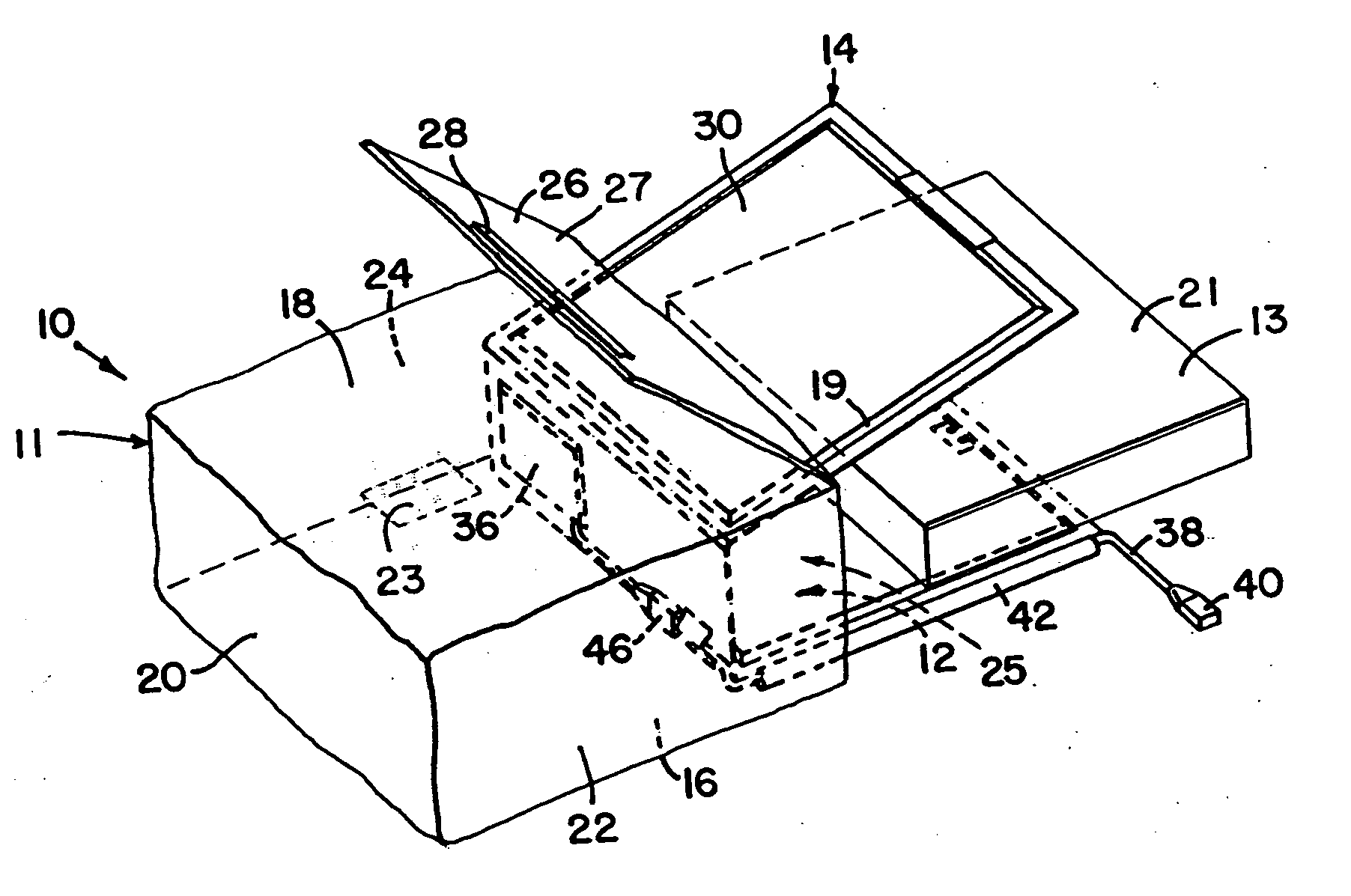
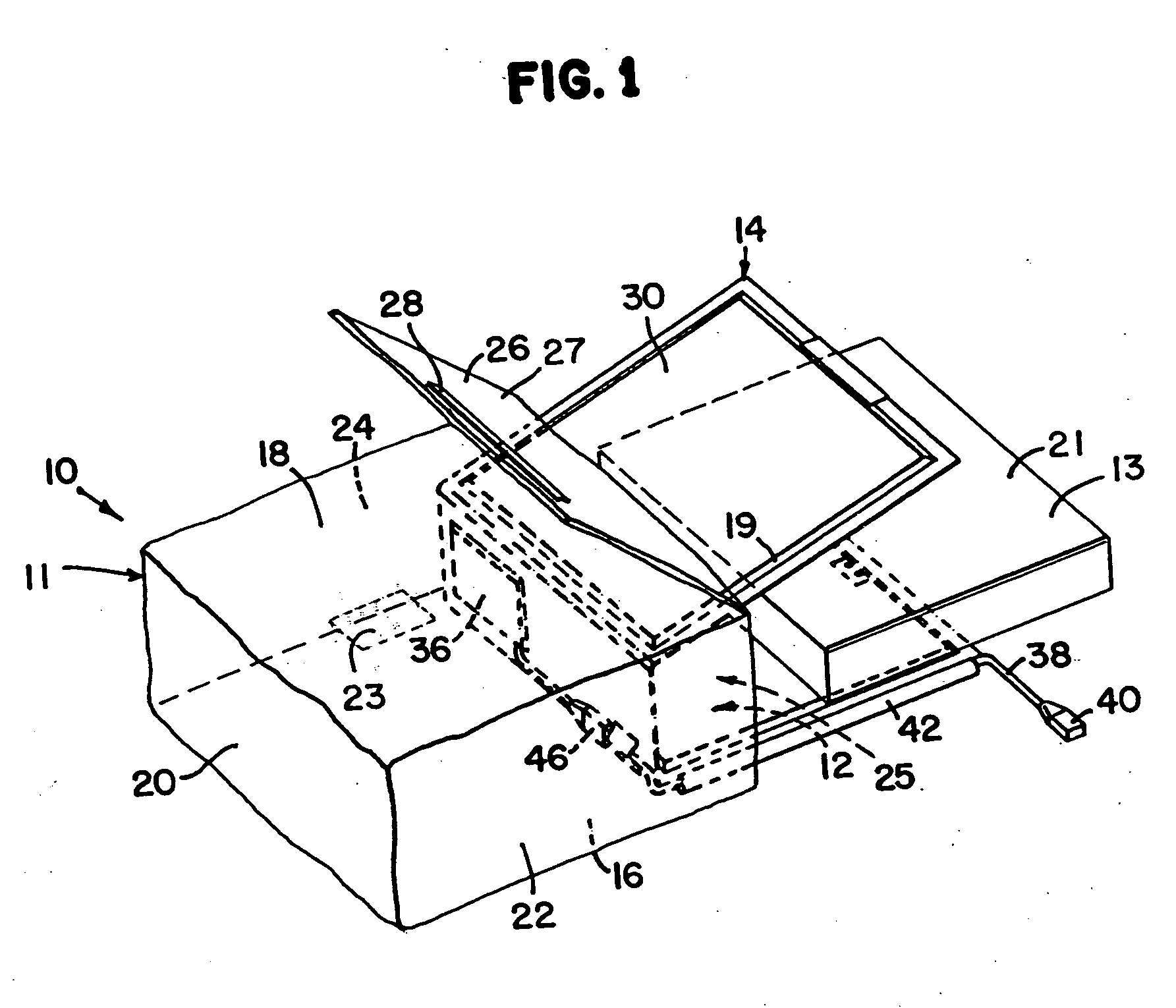
[0059] With reference now to the various figures in which identical elements are identically numbered throughout, a description of the preferred embodiment of the present invention will now be provided. The present invention will be described with reference to a delivery apparatus for food products. In particular, the present invention will be described with reference to a pizza delivery bag for transporting pizzas. It is customary to place cooked pizza in individual cardboard boxes. While the invention is being described in the context of a preferred embodiment, it will be appreciated that the invention can be used in a wide variety of applications for storing and / or transporting articles where it is desired to maintain the articles at an elevated temperature relative to ambient temperature.
[0060] Now referring to FIG. 1, a container 10 having an interior area 12 is shown with a heater 14 partially inserted into the interior area 12. The container 10 can be any device having a plu...
PUM
Abstract
A delivery apparatus is provided according to one aspect of the invention. The delivery apparatus includes a container sized to be carried during a food delivery. The container defines an interior area and an opening to the interior area. The delivery apparatus further includes an electrical device configured to change the temperature of the interior area relative to an ambient temperature. The electrical device is positioned within the interior area of the container. The electrical device is powered by a power source remote from the container. The electrical device is configured to remain with the container during a food delivery, and is transportable. The delivery apparatus further includes a connection apparatus residing within the delivery apparatus. The connection apparatus includes a retractable connection pad electrically connected to the electrical device. The pad is movable between a retracted position and an exposed position, and is biased in the retracted position by a biasing member. The pad is extendable to the exposed position for connection to the power source.
Description
CROSS REFERENCE TO RELATED APPLICATIONS [0001] This application is a continuation in part of U.S. patent application Ser. No. 10 / 901,261 filed Jul. 27, 2004; which is a continuation of U.S. application Ser. No. 10 / 301,348 filed Nov. 20, 2002, now U.S. Pat. No. 6,861,628; which is a continuation of U.S. patent application Ser. No. 10 / 101,249 filed Mar. 18, 2002, now U.S. Pat. No. 6,555,799; which is a continuation of U.S. patent application Ser. No. 09 / 747,181 filed Dec. 21, 2000, now U.S. Pat. No. 6,384,387; which is a continuation in part of U.S. Patent application Ser. No. 09 / 611,761 filed Jul. 7, 2000, now U.S. Pat. No. 6,433,313; which is a continuation in part of U.S. patent application Ser. No. 09 / 504,550 filed Feb. 15, 2000, now U.S. Pat. No. 6,353,208. The entire disclosure of each of the above applications is incorporated herein by reference.FIELD OF THE INVENTION [0002] The invention relates to a delivery apparatus, a base station for powering a delivery apparatus, and a m...
Claims
Application Information
Patent Timeline
Application Date:The date an application was filed.
Publication Date:The date a patent or application was officially published.
First Publication Date:The earliest publication date of a patent with the same application number.
Issue Date:Publication date of the patent grant document.
PCT Entry Date:The Entry date of PCT National Phase.
Estimated Expiry Date:The statutory expiry date of a patent right according to the Patent Law, and it is the longest term of protection that the patent right can achieve without the termination of the patent right due to other reasons(Term extension factor has been taken into account ).
Invalid Date:Actual expiry date is based on effective date or publication date of legal transaction data of invalid patent.
Patent Type & Authority Applications(United States)