
Lighting device and lighting method

Active Publication Date: 2007-12-06
IDEAL IND LIGHTING LLC
View PDF12 Cites 206 Cited by
  • Summary
  • Abstract
  • Description
  • Claims
  • Application Information

AI Technical Summary

Benefits of technology

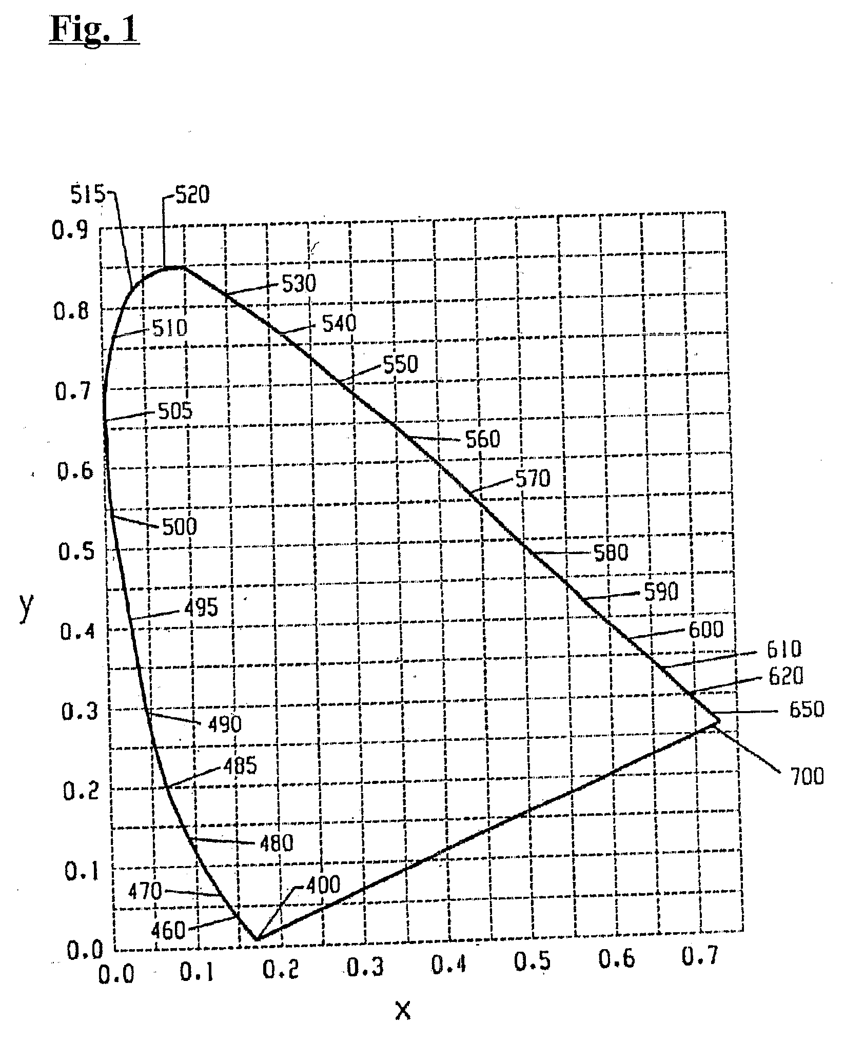
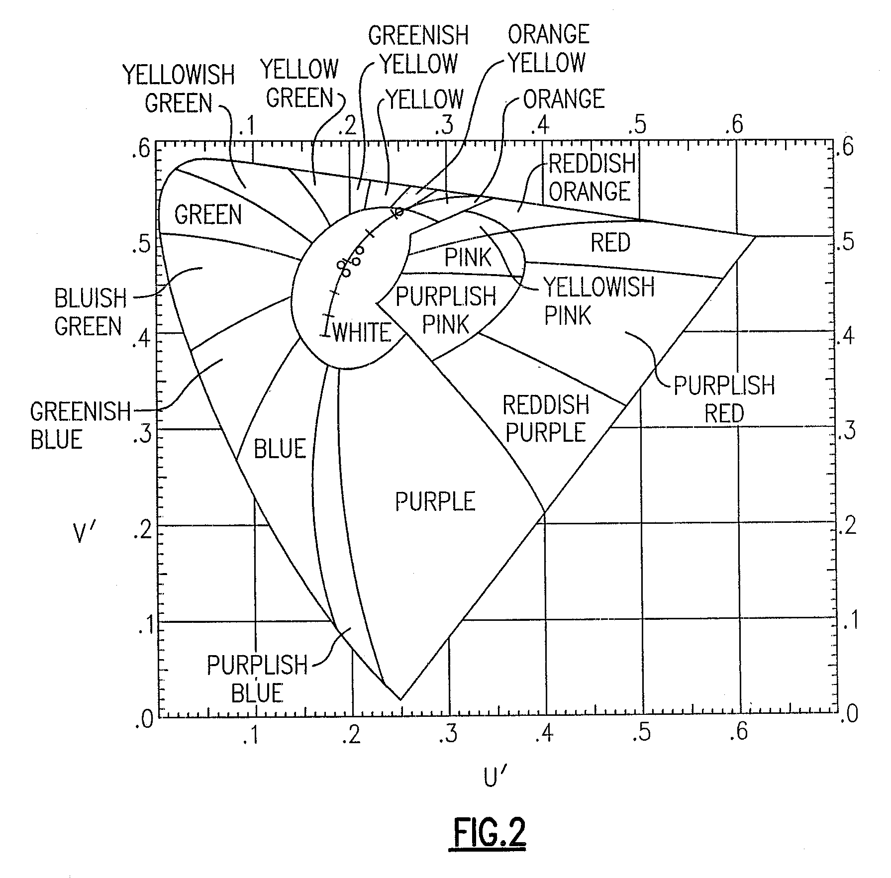
[0049] By providing a lighting device according to the first aspect or the second aspect of the present invention, it is possible to more efficiently adjust the combined illumination from the first group of packages (i.e., to alter its u′, v′ coordinates by removing (or reinserting) fewer packages), than would be the case where the u′, v′ coordinates of more of the packages are closer to the u′, v′ coordinates of the combined illumination, i.e., it is easier to navigate on the u′ v′ chart (or, of course, on the x, y chart, where the corresponding distances could readily be converted by those skilled in the art).
[0055] In some embodiments of the present invention, there are further provided one or more thermistors which detect temperature and, as temperature changes, cause one or more current adjusters and / or one or more switches to automatically interrupt and / or adjust current passing through one or more respective power lines in order to compensate for such temperature change. In general, 600 nm to 630 nm light emitting diodes get dimmer as their temperature increases—in such embodiments, fluctuations in intensity caused by such temperature variation can be compensated for.

Problems solved by technology

There exist “white” LED light sources which are relatively efficient but which have poor color rendering, typically having CRI Ra values of less than 75, and which are particularity deficient in the rendering of red colors and also to a significant extent deficient in green.
Typically, such white LED light sources have a color temperature of approximately 5000 K, which is generally not visually comfortable for general illumination, which however may be desirable for the illumination of commercial produce or advertising and printed materials.

Method used


Image

  • Lighting device and lighting method
  • Lighting device and lighting method
  • Lighting device and lighting method

Examples


Embodiment Construction

[0092] The expression “directly or switchably electrically connected” means “directly electrically connected” or “switchably electrically connected.”

[0093] A statement herein that two components in a device are “directly electrically connected,” means that there are no components electrically between the components, the insertion of which materially affect the function or functions provided by the device. For example, two components can be referred to as being electrically connected, even though they may have a small resistor between them which does not materially affect the function or functions provided by the device (indeed, a wire connecting two components can be thought of as a small resistor); likewise, two components can be referred to as being electrically connected, even though they may have an additional electrical component between them which allows the device to perform an additional function, while not materially affecting the function or functions provided by a device ...


PUM


Abstract

A lighting device, comprising a first group of solid state light emitters and a first group of lumiphors, wherein at least some of the first group of solid state light emitters are contained in a first group of packages, each of which also comprises at least one of the first group of lumiphors. If all of the first group of solid state light emitters which are contained in the first group of packages are illuminated and / or if current is supplied to a power line, (1) a combined illumination from the first group of packages would, in the absence of any additional light, have color coordinates on a 1976 CIE Chromaticity Diagram which define a first point, and (2) at least 20% of the packages would emit light having color coordinates spaced from the first point. Also, methods of lighting.

Description

CROSS-REFERENCE TO RELATED APPLICATIONS [0001] This application claims the benefit of U.S. Provisional Patent Application No. 60 / 793,530, filed on Apr. 20, 2006, entitled “LIGHTING DEVICE AND LIGHTING METHOD” (inventors: Gerald H. Negley and Antony Paul van de Ven), the entirety of which is hereby incorporated by reference.FIELD OF THE INVENTION [0002] The present invention relates to a lighting device, in particular, a device which includes one or more solid state light emitters and which may optionally also include one or more luminescent materials (e.g., one or more phosphors). The present invention is also directed to lighting methods. BACKGROUND OF THE INVENTION [0003] A large proportion (some estimates are as high as twenty-five percent) of the electricity generated in the United States each year goes to lighting. Accordingly, there is an ongoing need to provide lighting which is more energy-efficient. It is well-known that incandescent light bulbs are very energy-inefficient ...

Claims


Application Information

Patent Timeline
IPC IPC(8): H01L33/00H01L21/64F21K99/00
CPCF21Y2101/02F21K9/00F21K9/62F21Y2115/10
Inventor VAN DE VEN, ANTONY PAULNEGLEY, GERALD H.
Owner IDEAL IND LIGHTING LLC
Learn More