
Window-Integrated Antenna in Vehicles

a technology of integrated antennas and vehicles, applied in the direction of antennas, antenna details, antenna adaptation in movable bodies, etc., can solve the problems of unnecessarily increasing capacitance, lms reception deterioration, performance deterioration cannot be tolerated

Inactive Publication Date: 2007-12-06
ROBERT BOSCH GMBH
View PDF9 Cites 9 Cited by
  • Summary
  • Abstract
  • Description
  • Claims
  • Application Information

AI Technical Summary

Benefits of technology

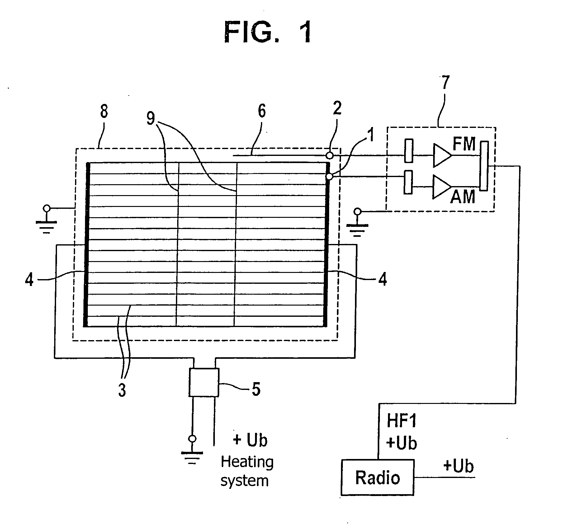
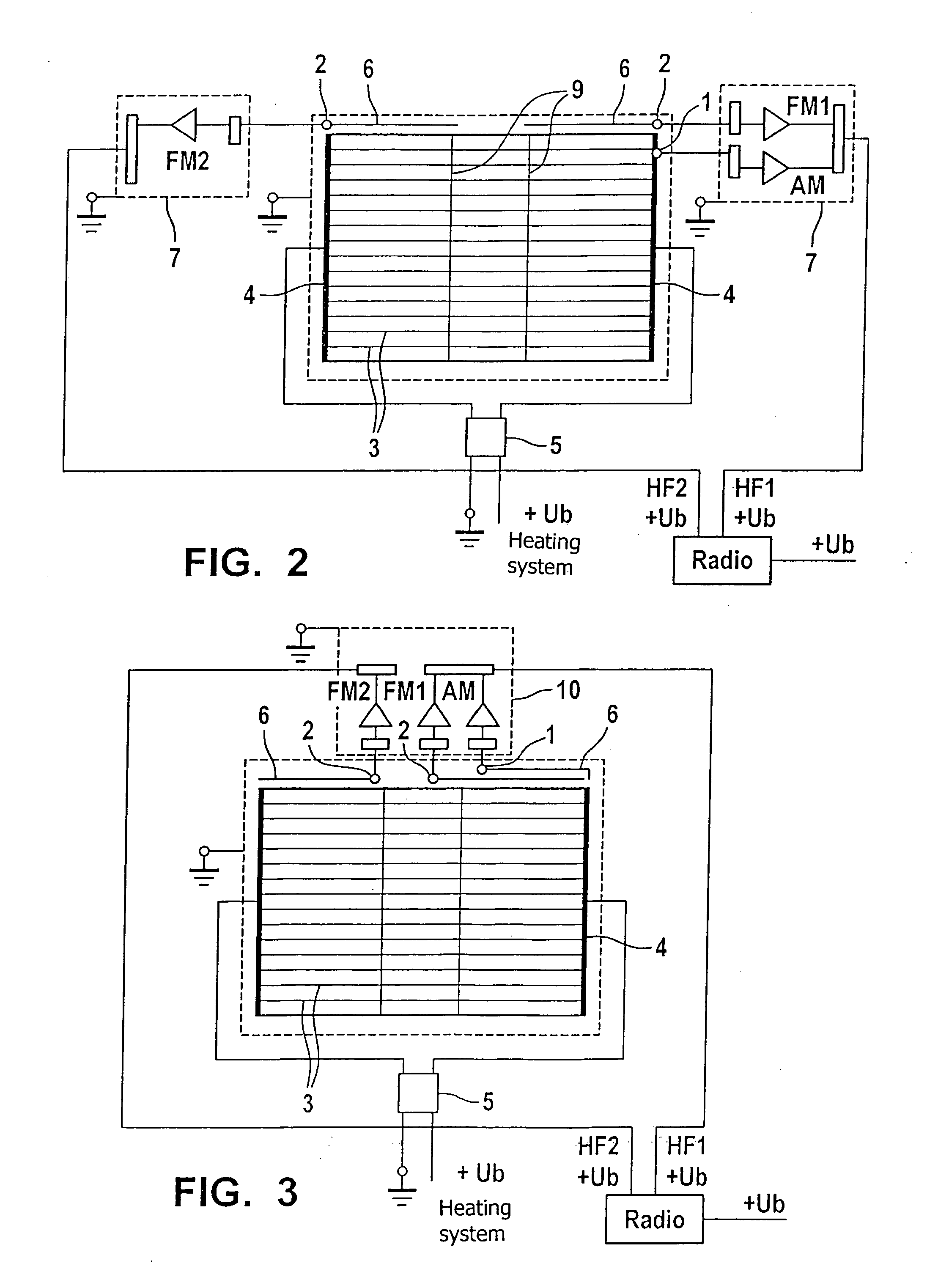
[0007] The measures of the exemplary embodiment of the present invention, i.e., using a heating conductor field, which is provided at least for FM reception, but also for LMS reception, at least one decoupling element being provided for FM reception which has a high-frequency, low-resistance, non-galvanic connection to the heating conductor field, make it possible to receive LMS and diverse FM signals using a conductor structure in a single window pane which is applied through a single screen via a common screen printing method, without having to forego complete heating of the entire window, particularly in the area which is not covered by black print (outer edge of the window).
[0011] A further advantage of the exemplary embodiment of the present invention is cost-effective manufacture. In contrast to other embodiments, only one single window pane needs to be manufactured. Another advantage is the integrated and thus simple configuration of passive and active circuit components which provide separate signal paths for the different frequency bands, but which may be placed in one single housing. In addition to a minimum of mechanical components, this also results in minimal wiring in the vehicle and thus in substantial weight reduction.

Problems solved by technology

This capacitance is unnecessarily increased by more than 10% due to connected electronic components, so that the LMS reception deteriorates because the reception signals flow off toward ground via the electronic module.
This performance deterioration cannot be tolerated in regions where AM is heavily used (e.g., USA, Mexico).
The equivalent capacitance of the connected electronic module is not effective for LMS frequencies due to a decoupling element having a high-frequency, low-resistance, non-galvanic contact, thus making the LMS reception optimal.

Method used


Image

  • Window-Integrated Antenna in Vehicles
  • Window-Integrated Antenna in Vehicles
  • Window-Integrated Antenna in Vehicles

Examples


Embodiment Construction

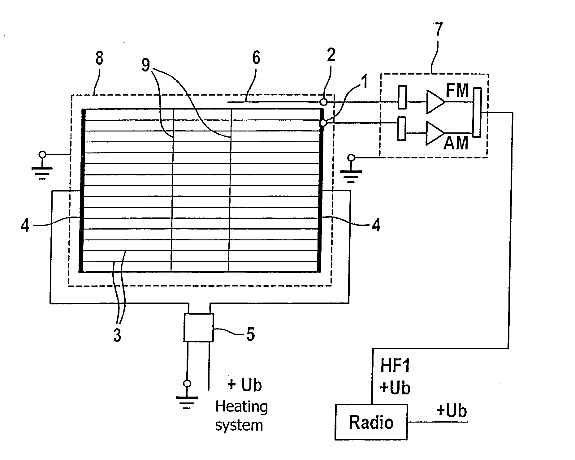
[0019]FIG. 1 shows a window-integrated antenna made up of heating conductors 3, running parallel to one another, which each meet a busbar 4 at their left and right ends. The heating conductor field formed in this way is supplied with heating current (Ub heating) via a filter element 5. Antenna connection point 1 is galvanically linked to the heating conductor field and implements the LMS reception. Contacting takes place at any point, may be, however, at the upper outer edge of the heating conductor field. Antenna connection point 2 is galvanically linked to a decoupling element 6. Decoupling element 6 may be made up of a conductor, which runs essentially parallel to at least one boundary of the heating conductor field which is not formed by busbars 4. The decoupling element may have any shape; it should, however, be a conductor formation made up of straight-line conductor segments. The FM reception is made possible via decoupling element 6. However, decoupling element / conductor for...


PUM


Abstract

In a window-integrated antenna in vehicles including a heating conductor field, which is provided for both FM reception as well as LMS reception, a decoupling element for the FM reception is provided which has a high-frequency, low-resistance, but non-galvanic connection to the heating conductor field.

Description

FIELD OF THE INVENTION [0001] The present invention is directed to a window-integrated antenna in vehicles. BACKGROUND INFORMATION [0002] The heating field of the window has been and is used as the antenna structure in window-integrated antennas in vehicles. U.S. Pat. No. 6,498,588 B1 discusses the heating field for both FM and TV reception. A conductor loop, which is not connected to the heating field, is additionally provided for LMS (long, medium, short wave) reception on the upper edge of the window. [0003] A significant disadvantage of such a system is believed to be the necessity of a surface, e.g., in the upper area of the window, which, due to non-existing heating conductors, cannot be heated and therefore cannot be defrosted. The available heatable area may be unacceptably small, particularly in passenger cars having small windows. [0004] The heating conductors run essentially horizontally and essentially parallel to the metallic boundaries of the window (body). Interferenc...

Claims


Application Information

Patent Timeline
Patent Type & Authority Applications(United States)
IPC IPC(8): H01Q1/32H01Q1/12
CPCH01Q1/1278
Inventor HOFFMEISTER, MARKUSKUEHNE, RAINERTHOLE, MICHAEL
Owner ROBERT BOSCH GMBH
Learn More