
Method for Forming 2-Dimensional Code by Laser Marking and Laser Marking Device

a laser marking and code technology, applied in the field of 2dimensional code formation by laser marking and laser marking devices, can solve the problems of difficult to accurately recognize 2-dimensional codes, increase costs, lack of convenience, etc., and achieve the effect of reducing costs and improving accuracy of reading 2-dimensional codes

Inactive Publication Date: 2007-12-06
ARAI HELMET LTD
View PDF7 Cites 29 Cited by
  • Summary
  • Abstract
  • Description
  • Claims
  • Application Information

AI Technical Summary

Benefits of technology

[0023] When doing this way, an area that is judged as bright cell in the code symbol of the non-reversed 2-dimensional code as an original image is marked to be bright and an area that is judged as code color cell is remained as dark. Thereby, even when the generated color of a portion on which laser beam is applied is brighter than the portion on which laser beam is not applied, non-reversed 2-dimensional code can be marked. Thus, since a bright / dark reversing function of reading device is not required and it is possible to use a conventional reading device, great cost reduction can be realized.
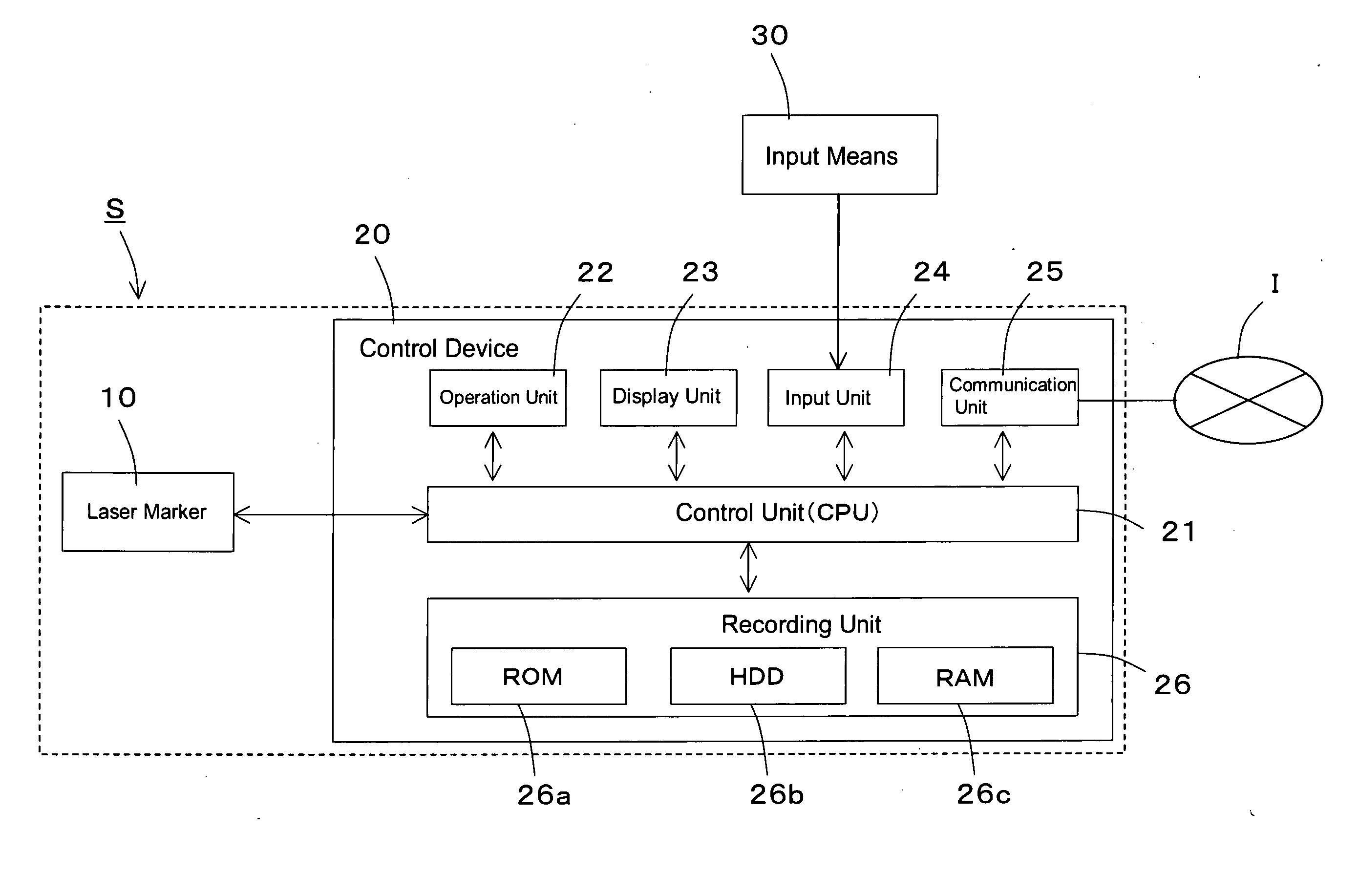
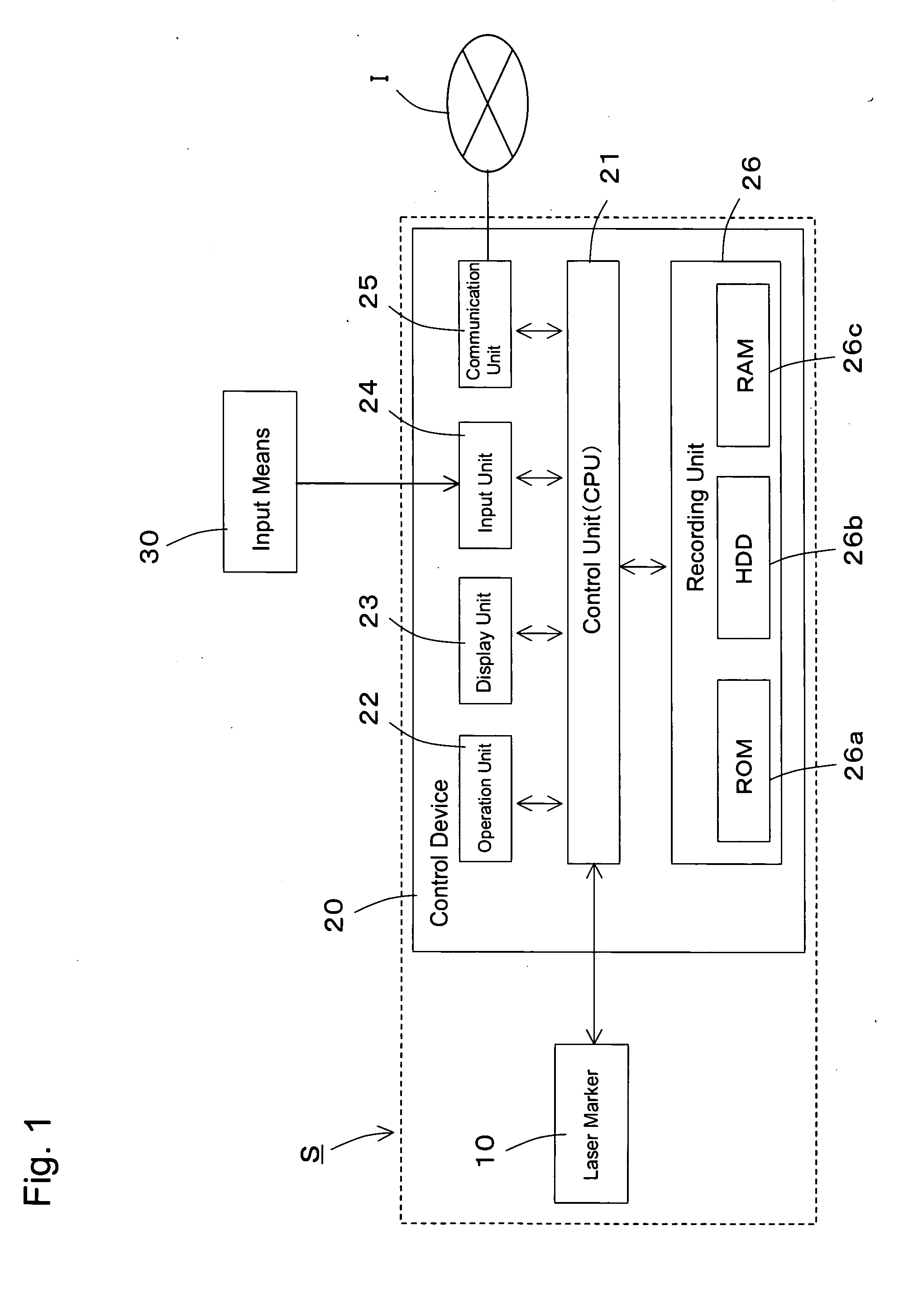
[0040] Here, it is desirable to construct the control means so that it has a display unit that is possible to display the code symbol and the reversed code symbol. By doing this, operators can execute marking and preparation of the work while checking an image of the code symbol and the reversed code symbol.

Problems solved by technology

However, in 2-dimensional code formation technology by laser marking, it has not been executed to form always the non-reversed 2-dimensional code against the marked materials of any kind by executing a bright / dark conversion of 2-dimensional code's marking data corresponding to the marked materials.
Further, when it is required to use either an ordinary reading device or a reading device equipped with bright / dark reversing function depending on the type of material, there have been a problem of lack of convenience.
In addition, if it is always required to use the highly functional reading device equipped with bright / dark reversing function, there has been a problem of cost increase.
Thus, in case of bright / dark reversed 2-dimensional code, there has been such a problem that boundary of area in which 2-dimensional code has been marked is hard to be accurately recognized and it becomes impossible to execute reading the 2-dimensional code.
Therefore, for example, when the object behind the transparent material is something white, contrast between the color generated portion by laser beam and the body portion where laser beam is not applied becomes small, thereby the boundary of this portion becomes hard to be recognized when 2-dimensional code is taken in as an image data by CCD camera or laser scanner, etc.
Thus, such a problem that read out of 2-dimensional code becomes impossible occurs.

Method used


Image

  • Method for Forming 2-Dimensional Code by Laser Marking and Laser Marking Device
  • Method for Forming 2-Dimensional Code by Laser Marking and Laser Marking Device
  • Method for Forming 2-Dimensional Code by Laser Marking and Laser Marking Device

Examples


second embodiment

THE SECOND EMBODIMENT

Method for Forming 2-Dimensional Code by Laser Marking

[0129] In the first embodiment, the reversed code symbol 1R is generated by executing bright / dark reversing conversion and by attaching the quiet zone to its periphery under the condition that the code symbol 1 of the 2-dimensional code generated or acquired first is judged that the color of marking portion is brighter than the body color as the result of judgment based on generated color information.

[0130] In the second embodiment, judgment is executed first based on generated color information without generating the code symbol of non-reversed 2-dimensional code. When the color of marking portion is judged to be brighter than the body color as the result, the pattern of reversed code symbol 1R is directly generated without executing bright / dark reversing conversion. And, when the color of marking unit is judged to be darker than the body color as the result, the process to generate the code symbol 1 of no...

third embodiment

THE THIRD EMBODIMENT

Method for Forming 2-Dimensional Code by Laser Marking

[0136] In the first and the second embodiment, first, judgment based on the generated color information is executed. And when the color of marking unit is judged to be brighter than the body color as the result, reversed code symbol 1R is generated and the marking data is generated based on this reversed code symbol 1R. At this time, the marking data is generated so that the laser beam may be applied to the dark cell area and the dots may be formed or scanned among the bright and dark cell array.

[0137] In the third embodiment, reversed code symbol 1R is not generated. That is, first, the 2-dimensional code is generated or acquired based on the acquired data. Then, judgment based on the generated color information is executed. And, when the color of marking portion is judged to be brighter than the body color as the result, the pattern to which a bright color quiet zone is added around the non-reversed code s...


PUM

PropertyMeasurementUnit
coloraaaaaaaaaa
widthaaaaaaaaaa
areaaaaaaaaaaa

Abstract

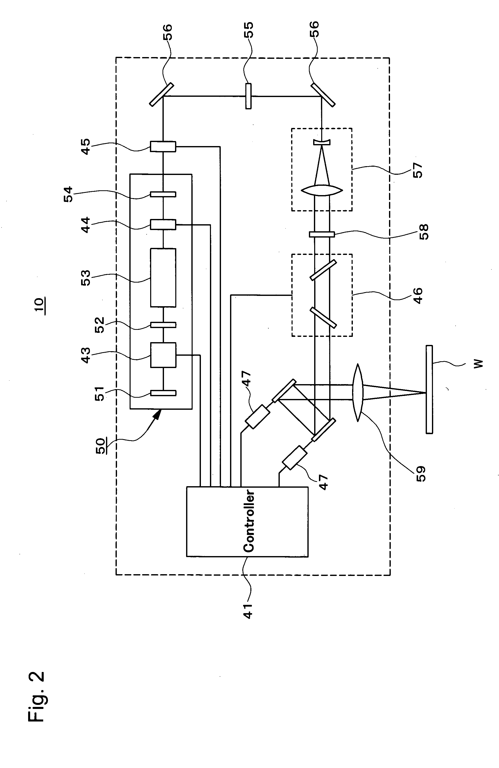
It is judged whether a marking unit formed on a material becomes a bright mark or a dark mark. Based on this judgment, for the work W of a material in which the marking unit becomes a bright mark, the code symbol of the 2-dimensional code of the original image is bright / dark-reversed to generate a reversed code symbol 1R. By doing this, a laser marker 10 is controlled so as to apply a laser beam to the cell of the background portion without applying the laser beam on the cell of the code portion. On the other hand, in the case of the normal material in which the marking unit becomes a dark mark, the laser marker 10 is controlled to apply the laser beam to the cell of the code portion without applying the beam to the cell of the background portion.

Description

FIELD OF THE INVENTION [0001] The present invention relates to a method for forming 2-dimensional code by laser marking and a laser marking device, in particular to a method for forming 2-dimensional code that is possible to form 2-dimensional code not bright / dark-reversed by laser marking and a laser marking device. BACKGROUND OF THE INVENTION [0002] Conventionally, when forming a 2-dimensional code by laser marking, a marking pattern has been formed by applying a laser beam to a black cell (a portion with a code color) and not applying the laser beam to a white cell (portion with a background color) constructing a code symbol of 2-dimensional code. [0003] As described above, when the laser beam is applied, a portion where the laser beam is applied generates a color and a portion where the laser is not applied remains a material's color, which generates a contrast of bright and dark between the color generated portion and the material's color remained portion. In this way, 2-dimens...

Claims


Application Information

Patent Timeline
Patent Type & Authority Applications(United States)
IPC IPC(8): G06K1/12B41J2/00B23K26/00B60R22/03
CPCG06K1/126Y10T74/1967
Inventor SATO, KAZUO
Owner ARAI HELMET LTD
Learn More