
Control system for static neutralizer

Inactive Publication Date: 2007-12-06
MKS INSTR INC
View PDF4 Cites 53 Cited by
  • Summary
  • Abstract
  • Description
  • Claims
  • Application Information

AI Technical Summary

Benefits of technology

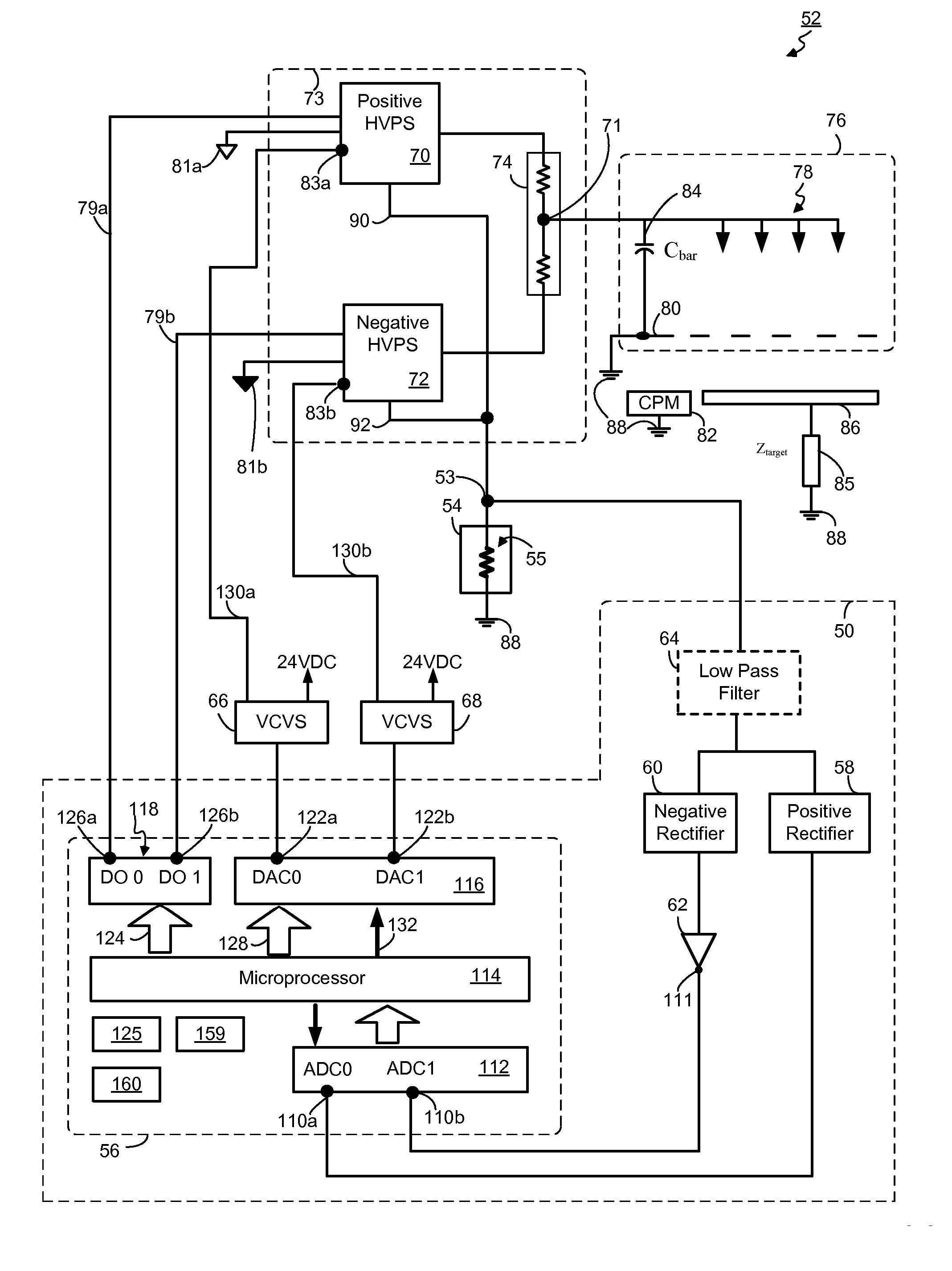
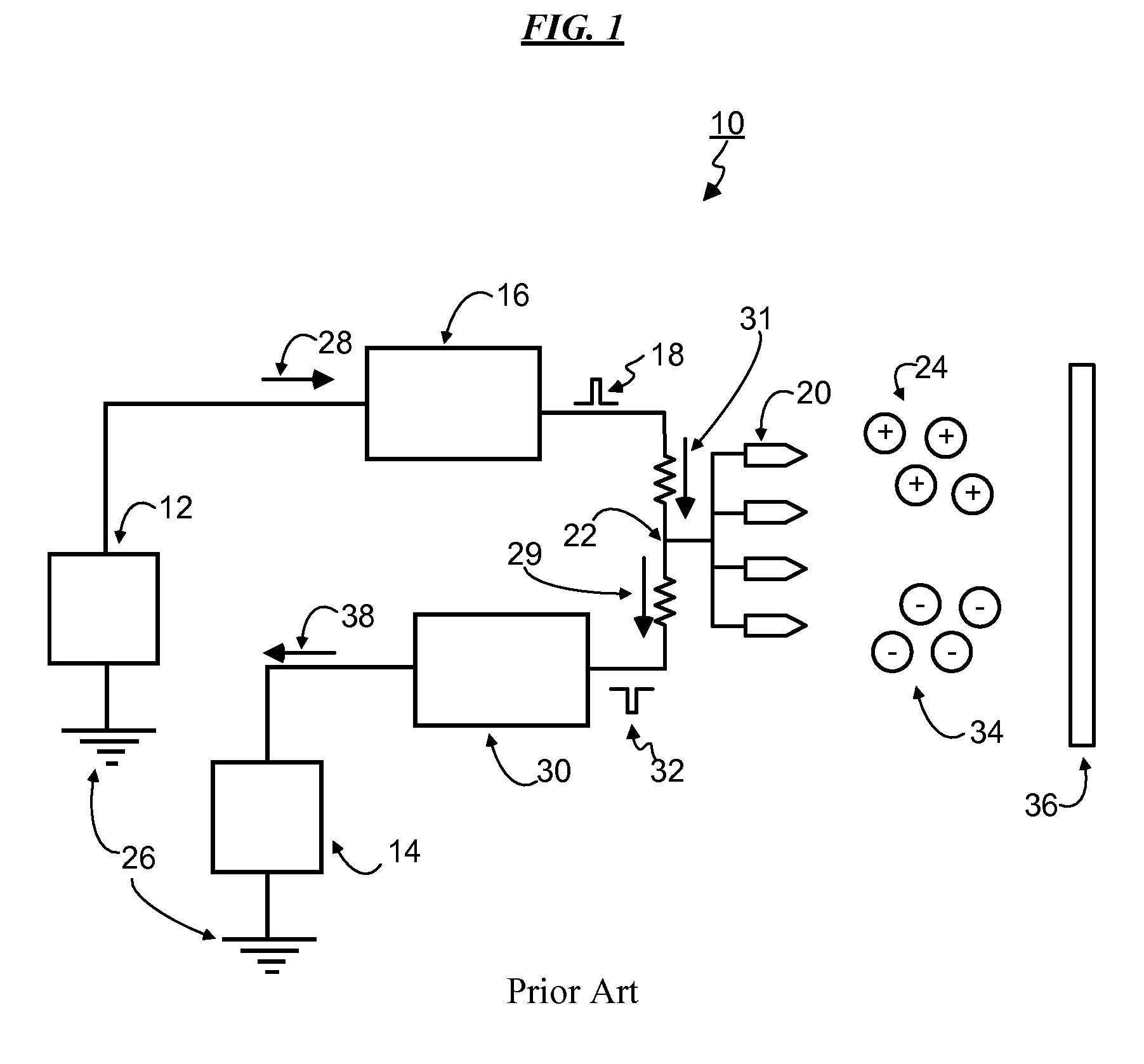
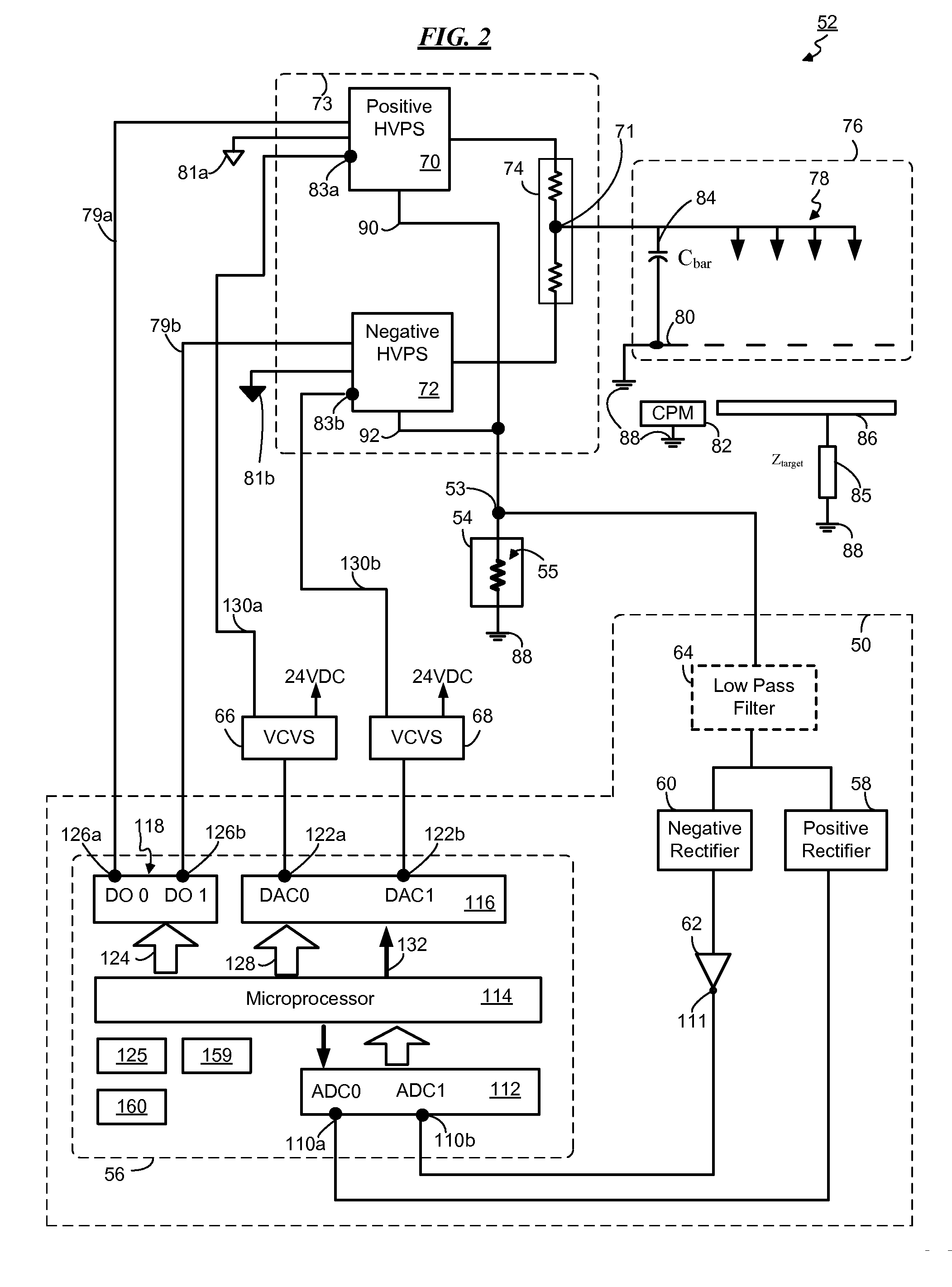
[0023] The present invention pertains to various embodiments for managing ion current balance by independently controlling positive ion current and negative ion current

Problems solved by technology

However, the ion balance of a static neutralizer is affected by many factors and may change overtime.
For example, the emitters may accumulate debris due to air or gas borne contaminants, or the emitters may degrade or erode.
This change in ion balance, named ion balance drift, if left uncorrected, may drift out of a specified voltage range, disrupting the optimal ion balance and decreasing the efficiency of the static neutralizer.
However, this approach is less than optimal since it requires the static neutralizer to be placed out of operation during cleaning, which may interrupt production and cause added expense and delay.
But using return currents to determine and control ion balance results in ion current and ion measuring problems if both power supplies energize the same set of emitters through one high voltage bus.
Using separate sets of positive and negative emitters, however, leads to another set of problems, such as increasing static neutralizer production complexity, and therefore, cost.
Another problem with the solution discussed above includes measurement error and measurement stability.
Measuring positive and negative return currents, calculating their differences, and then using the differences to determine ion balance in a static neutralizer is not optimal because these return currents are relatively large when compared to their differences.
Thus, prior solutions that use this approach suffer from balance errors that are determined by the magnitude of the two large numbers rather than the magnitude of the ion balance itself.
A further problem concerns non-representative waveform sampling.
Another problem involves interaction between the ionizer's feedback adjustment and balance within a target zone.

Method used


Image

  • Control system for static neutralizer
  • Control system for static neutralizer
  • Control system for static neutralizer

Examples


Embodiment Construction

[0035] In the following detailed description, for purposes of explanation, numerous specific details are set forth to provide a thorough understanding of the various embodiments of the present invention. Those of ordinary skill in the art will realize that these various embodiments of the present invention are illustrative only and are not intended to be limiting in any way. Other embodiments of the present invention will readily suggest themselves to such skilled persons having benefit of the disclosure herein.

[0036] In addition, for clarity purposes, not all of the routine features of the embodiments described herein are shown or described. It is appreciated that in the development of any such actual implementation, numerous implementation-specific decisions must be made to achieve the developer's specific goals. These specific goals will vary from one implementation to another and from one developer to another. Moreover, it will be appreciated that such a development effort migh...


PUM


Abstract

The present invention pertains to various embodiments for managing ion current balance by independently controlling positive ion current and negative ion current generated during static neutralization. In another embodiment, E-Field compensation may be provided. These embodiments disclose both method and apparatus implementations.

Description

CROSS REFERENCE TO RELATED APPLICATIONS [0001] This non-provisional application claims, pursuant to 35 U.S.C. 119(e), the benefit of provisional application 60 / 790, 424, filed 6 Apr. 2006 and entitled “Control System for Static Neutralizer”.BACKGROUND [0002] (1) Technical Field [0003] The present invention relates to static neutralizers, which are designed to eliminate or minimize static charge accumulation of an object. These static neutralizers compensate the static charge by generating bipolar air, or in some instances gas, ions and delivering these air or gas ions to a charged object. [0004] (2) Background Art [0005] A static neutralizer is commonly used to remove unwanted or destructive electro-static potential from a charged object, named “target”. Generally, a static neutralizer employs a set of electrodes, sometimes referred to as emitters, ionizing electrodes or corona electrodes, that each have a shape suitable for generating ions by corona discharge when a voltage, named ...

Claims


Application Information

Patent Timeline
IPC IPC(8): H01T23/00G11C17/00H05F3/06
CPCH01T23/00
Inventor GEFTER, PETEROLDYNSKI, EDWARDWARREN, BRIAN
Owner MKS INSTR INC
Learn More