Dose cup located near bend in final energy filter of serial implanter for closed loop dose control

a technology of dose control and final energy filter, which is applied in the field of ion implantation systems, can solve the problems of wafers becoming overdosed, dosimetry errors, and never perfect vacuum in the implanter

Active Publication Date: 2005-12-08
AXCELIS TECHNOLOGIES
View PDF15 Cites 33 Cited by
  • Summary
  • Abstract
  • Description
  • Claims
  • Application Information

AI Technical Summary

Benefits of technology

[0033] This approach enables the AEF cup current to be corrected for the shorter distance over which charge exchange can affect its reading compared to the End Station cup, which is done by the factor, (LAEF / (LES−LAEF). It also allows for that shorter distance to be corrected for the lower pressure in the AEF region, which is nominally done by the factor, (PAEF / PES). These two factors are applied to the fractional change in beam current between the two cups, (IAEF−IES) / IAEF). This approach may provide a non-empirical pressure compensation.

Problems solved by technology

However, the vacuum in an implanter is never perfect.
However, at high enough pressure, for example, increased pressure due to photoresist outgassing, charge exchange between the ion beam and the residual gas can cause dosimetry errors.
As a result, the wafer may become overdosed.
In addition, changes in the ion source output itself may result in some of the beam current variations measured at the dose cups.
Therefore, the use of such dose cup measurements to correct or compensate dose rates may be significantly hampered by these variables.

Method used


Image

  • Dose cup located near bend in final energy filter of serial implanter for closed loop dose control
  • Dose cup located near bend in final energy filter of serial implanter for closed loop dose control
  • Dose cup located near bend in final energy filter of serial implanter for closed loop dose control

Examples


Embodiment Construction

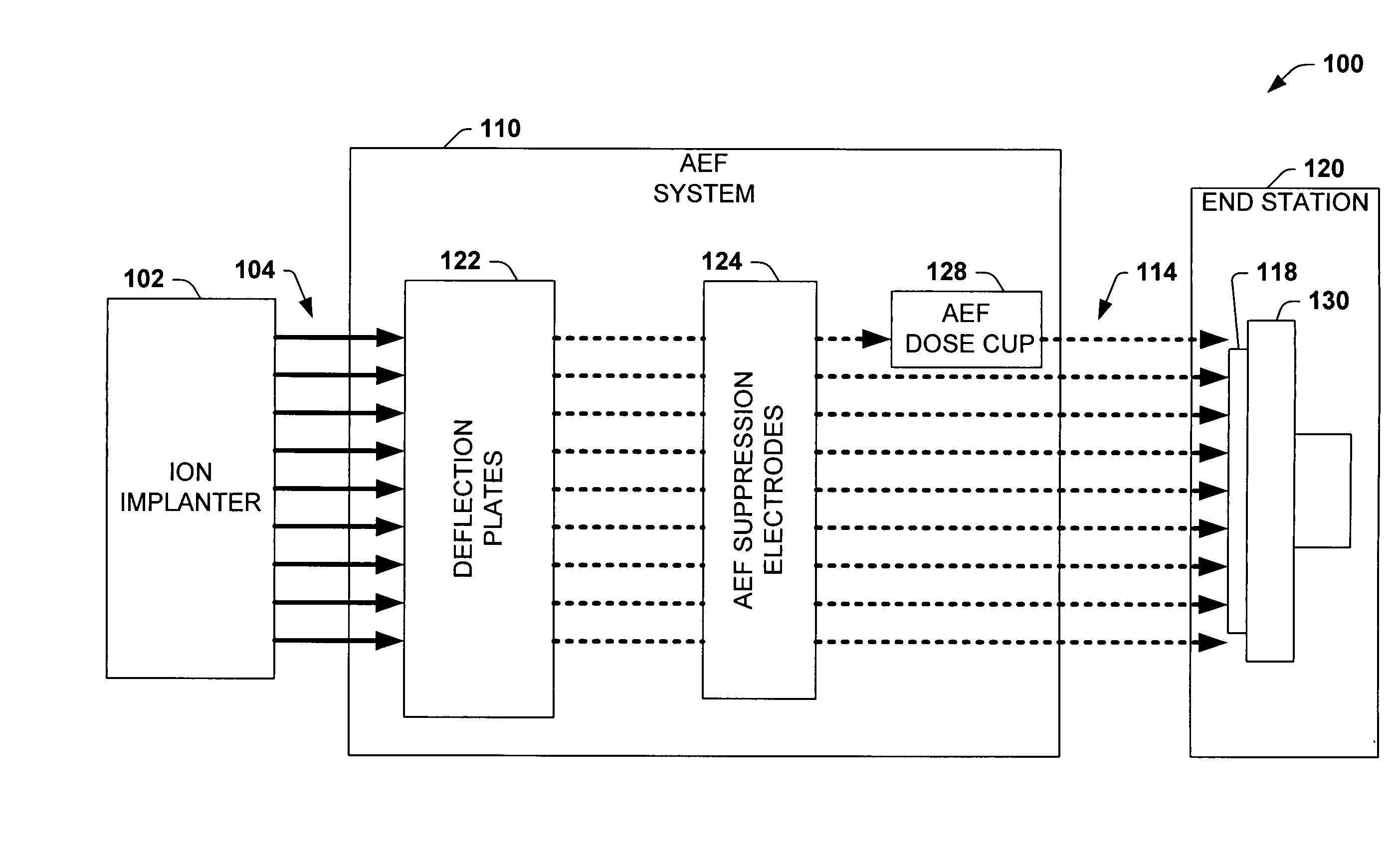
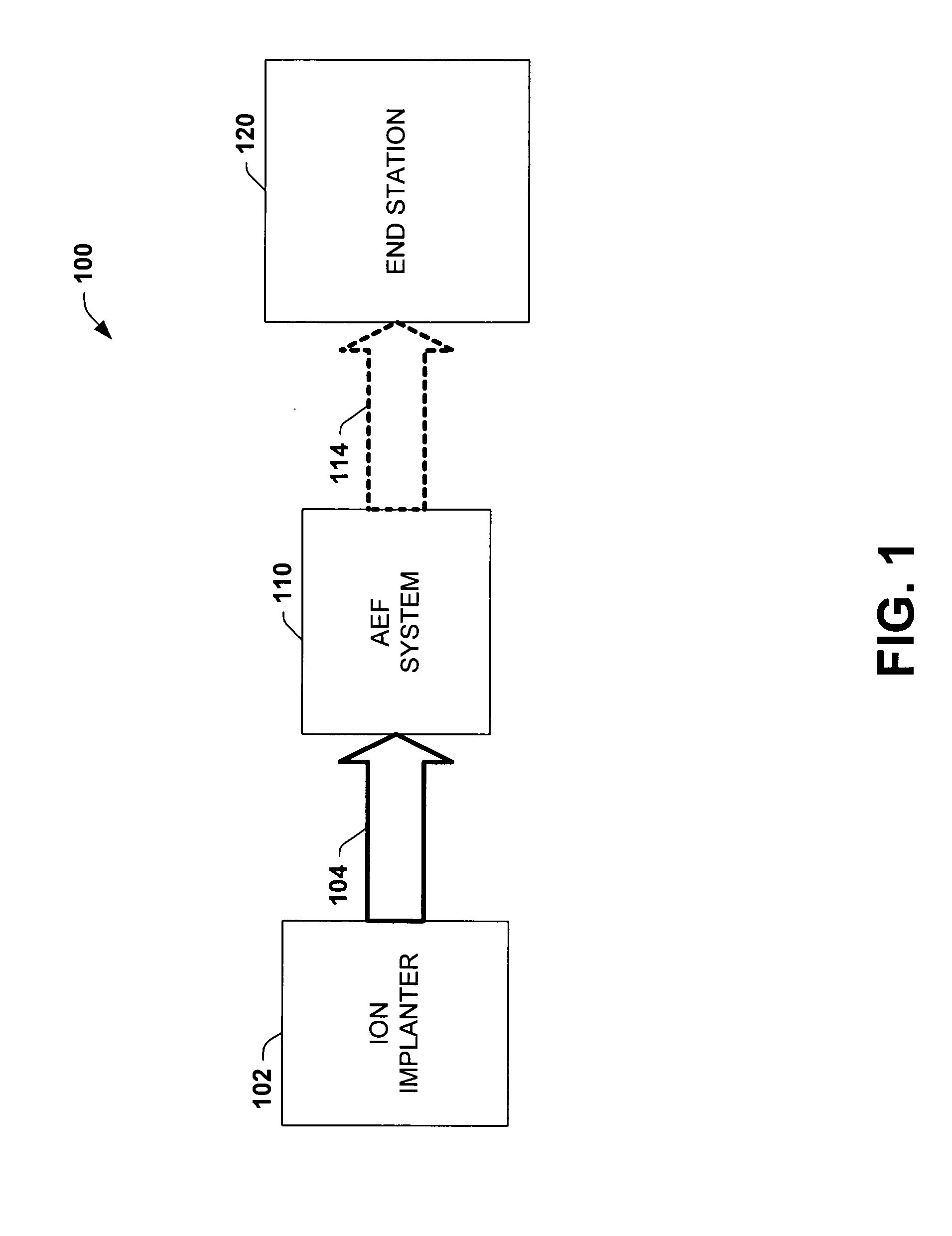
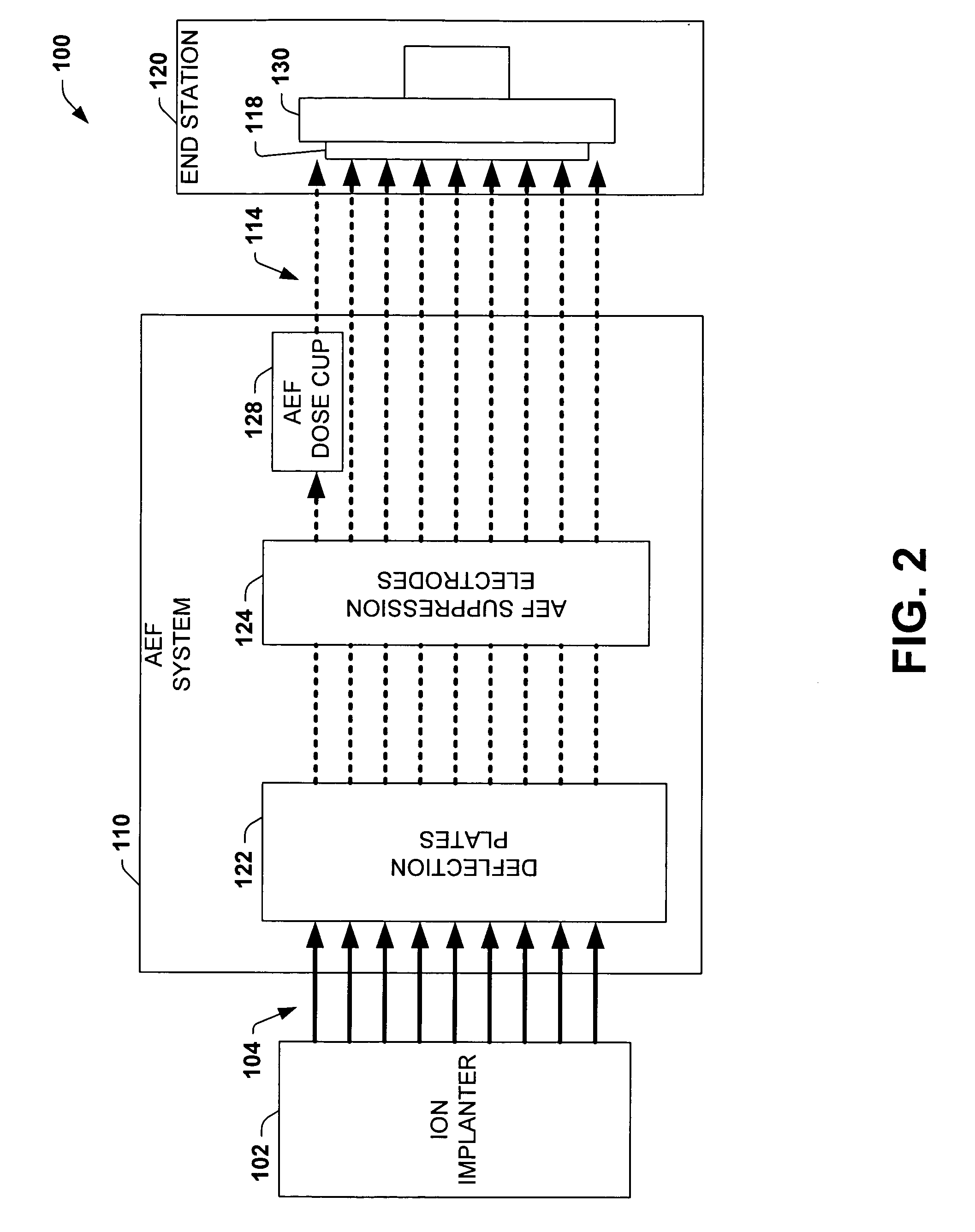
[0042] The present invention will now be described with reference to the drawings wherein like reference numerals are used to refer to like elements throughout. The invention provides a system and method for providing an accurate ion current measurement associated with the dose of a wafer for use in an ion implantation system. Such use may include dosimetry measurements, data recordings, and feedback to the system for closed loop control of, for example, the velocity of a wafer slow scan motion drive.

[0043] Dose control in the presence of high pressures in the process chamber, particularly due to photo-resist outgassing, requires a means of determining the effective implant beam current when some fraction of the beam ions have become neutralized on their path to the wafer. Traditionally this has been accomplished by measuring the pressure in the beam path and correcting the current measured at the wafer in the end station by estimating the fraction that has become neutral based on ...


PUM


Abstract

An ion implantation system having a dose cup located near a final energy bend of a scanned or ribbon-like ion beam of a serial ion implanter for providing an accurate ion current measurement associated with the dose of a workpiece or wafer. The system comprises an ion implanter having an ion beam source for producing a ribbon-like ion beam. The system further comprises an AEF system configured to filter an energy of the ribbon-like ion beam by bending the beam at a final energy bend. The AEF system further comprises an AEF dose cup associated with the AEF system and configured to measure ion beam current, the cup located substantially immediately following the final energy bend. An end station downstream of the AEF system is defined by a chamber wherein a workpiece is secured in place for movement relative to the ribbon-like ion beam for implantation of ions therein. The AEF dose cup is beneficially located up stream of the end station near the final energy bend mitigating pressure variations due to outgassing from implantation operations at the workpiece. Thus, the system provides accurate ion current measurement before such gases can produce substantial quantities of neutral particles in the ion beam, generally without the need for pressure compensation. Such dosimetry measurements may also be used to affect scan velocity to ensure uniform closed loop dose control in the presence of beam current changes from the ion source and outgassing from the workpiece.

Description

FIELD OF THE INVENTION [0001] The present invention relates generally to ion implantation systems, and more particularly to a system and method for ion dose measurement and compensation in the presence of photoresist outgassing, pressure and ion source fluctuations in a serial ion implanter. BACKGROUND OF THE INVENTION [0002] In the manufacture of semiconductor devices, ion implantation is used to dope semiconductors with impurities. Ion beam implanters are used to treat silicon wafers with an ion beam, in order to produce n or p type extrinsic material doping or to form passivation layers during fabrication of an integrated circuit. When used for doping semiconductors, the ion beam implanter injects a selected ion species to produce the desired extrinsic material. Implanting ions generated from source materials such as antimony, arsenic or phosphorus results in “n type” extrinsic material wafers, whereas if “p type” extrinsic material wafers are desired, ions generated with source ...

Claims


Application Information

Patent Timeline
Patent Type & Authority Applications(United States)
IPC IPC(8): H01J37/05H01J37/317
CPCH01J37/3171H01J37/05
Inventor RATHMELL, ROBERT D.
Owner AXCELIS TECHNOLOGIES
Why Eureka
Try Eureka