
Internal Combustion Engine Having Common Power Source For Ion Current Sensing and Fuel Injectors

a technology of ion current sensing and fuel injectors, which is applied in the direction of electrical control, process and machine control, instruments, etc., can solve the problem of not providing a bias voltage for ion sense, and achieve the effect of shortening the dwell time, facilitating more agile ignition timing, and shortening the charge time of the ignition coil

Inactive Publication Date: 2009-04-23
FORD GLOBAL TECH LLC
View PDF65 Cites 32 Cited by
  • Summary
  • Abstract
  • Description
  • Claims
  • Application Information

AI Technical Summary

Benefits of technology

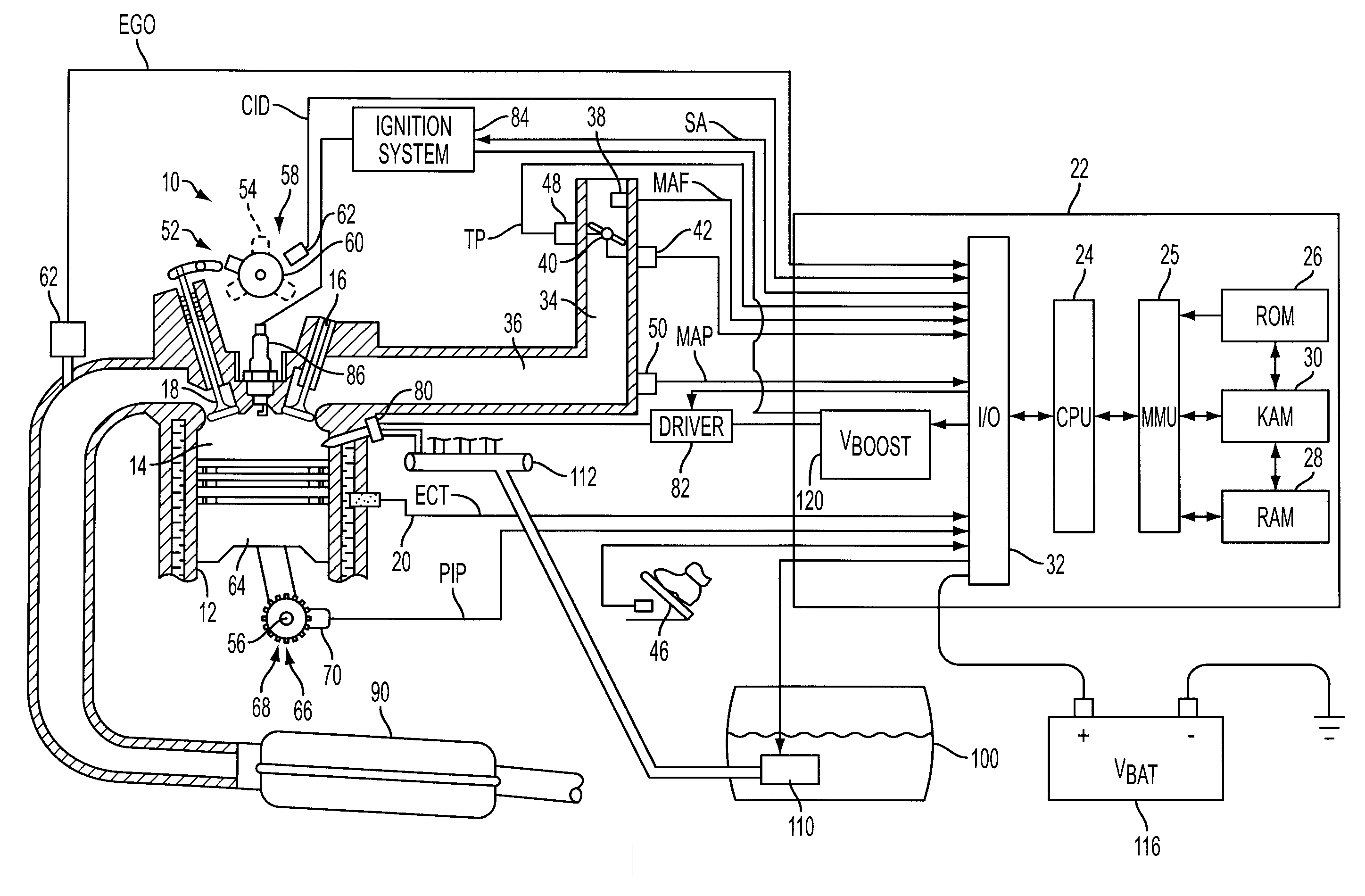
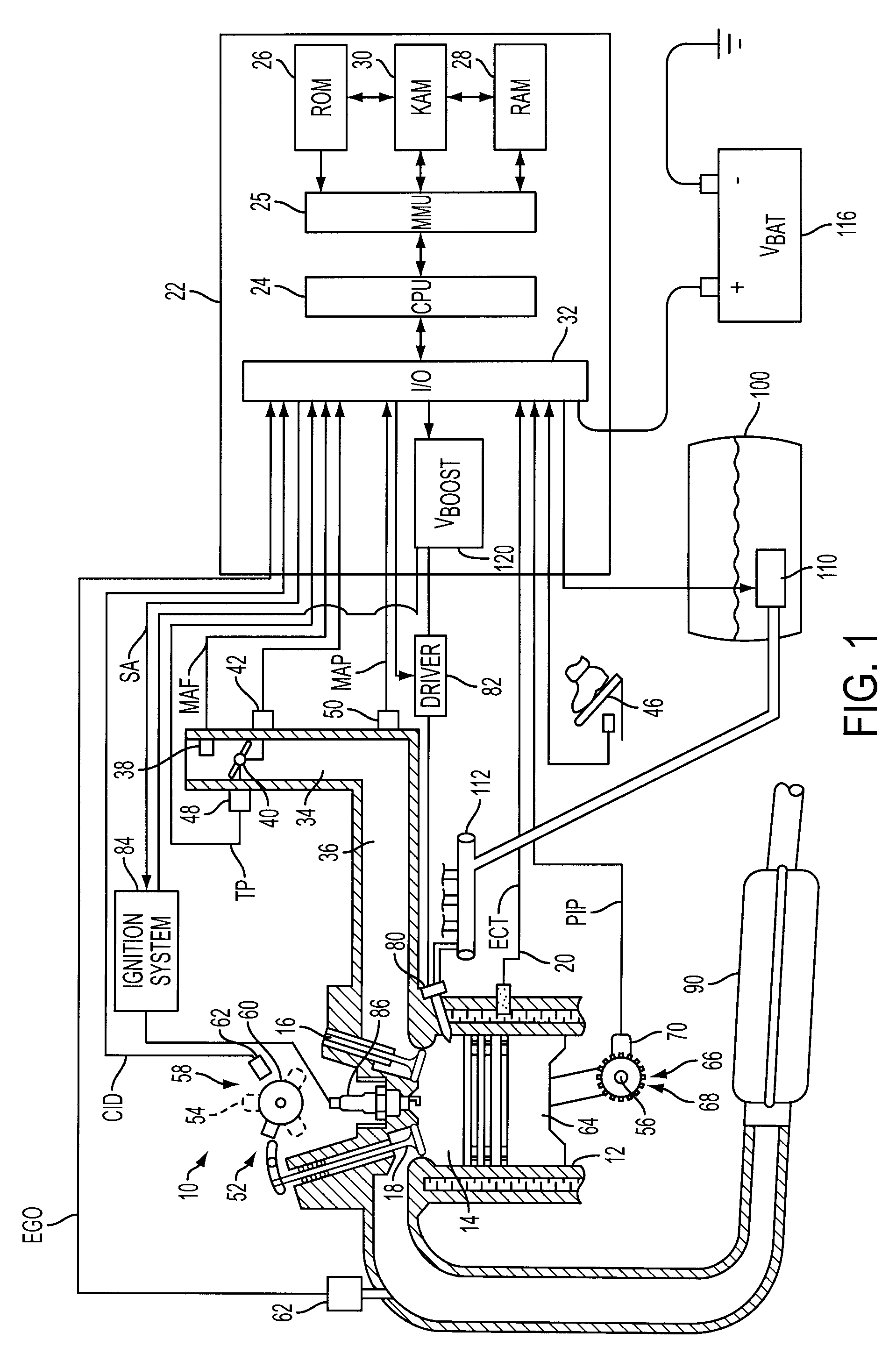
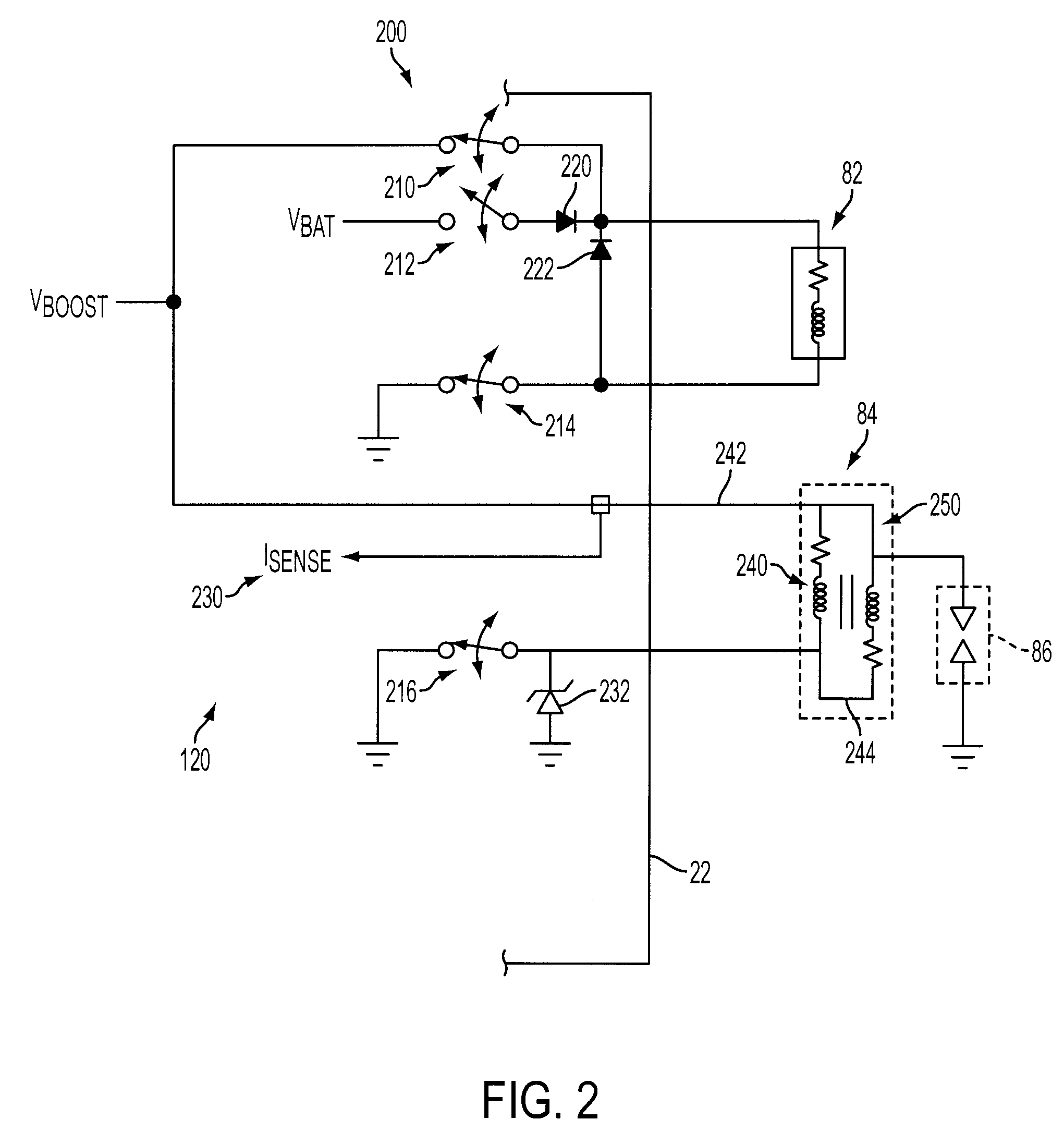
[0008]The present disclosure includes embodiments having various advantages. For example, the systems and methods of the present disclosure can provide ionization current sensing whether or not a spark plug discharge is provided, such as in compression ignition engines or operating modes, which include diesel engines and HCCI engines, for example. Using the high-voltage supply in spark-ignited applications for ignition coil charging facilitates more agile ignition timing with shorter ignition coil charge times and shorter dwell times, which in turn provides a larger time period for collecting ionization current data that is typically masked during coil / spark discharge. Using a single high-voltage power supply to actuate injectors and ionization sensing may provide a cost savings and reduce the number of control module pins required when the power supply is integrated in the engine controller.

Problems solved by technology

While suitable for some applications, these systems do not provide a bias voltage for ion sense when no spark is generated, such as during compression-ignition mode in HCCI engines, for example.

Method used


Image

  • Internal Combustion Engine Having Common Power Source For Ion Current Sensing and Fuel Injectors
  • Internal Combustion Engine Having Common Power Source For Ion Current Sensing and Fuel Injectors
  • Internal Combustion Engine Having Common Power Source For Ion Current Sensing and Fuel Injectors

Examples


Embodiment Construction

)

[0013]As those of ordinary skill in the art will understand, various features of the embodiments illustrated and described with reference to any one of the Figures may be combined with features illustrated in one or more other Figures to produce alternative embodiments that are not explicitly illustrated or described. The combinations of features illustrated provide representative embodiments for typical applications. However, various combinations and modifications of the features consistent with the teachings of the present disclosure may be desired for particular applications or implementations. The representative embodiments used in the illustrations relate generally to a, multi-cylinder, internal combustion engine with direct or in-cylinder injection and an ion sensing system that uses a spark plug, glow plug, or dedicated ionization sensor disposed within the cylinders. Those of ordinary skill in the art may recognize similar applications or implementations with other engine / v...


PUM


Abstract

A system and method for controlling operation of a multiple cylinder internal combustion engine having fuel injectors and an ionization current sensor include a high-voltage power supply connectable to, and supplying substantially the same nominal boosted voltage relative to nominal battery voltage to, the fuel injectors and ionization sensor during at least a portion of the engine operation.

Description

BACKGROUND[0001]1. Technical Field[0002]The present disclosure relates to systems and methods for supplying power for fuel injection and for ionization current sensing in internal combustion engines.[0003]2. Background Art[0004]Various types of spark-ignition, compression-ignition, and combination internal combustion engines use direct injection of fuel into the combustion chamber to reduce fuel consumption and feedgas emissions. These may include direct-injection spark-ignition (DISI) engines fueled by gasoline or gasoline / alcohol mixtures, compression-ignition engines fueled by diesel fuel, or combination engines fueled by gasoline or other fuels that may operate in a spark-ignition mode and a compression-ignition mode, sometimes referred to as homogeneous charge compression ignition (HCCI) mode, for example. A high-voltage power supply may be provided to generate the current required for desired performance of the fuel injectors for these applications, with representative voltage...

Claims


Application Information

Patent Timeline
IPC IPC(8): F02D41/00
CPCF02D35/021F02D41/20F02P2017/125F02P3/0435F02P17/12F02D2041/2003F02D41/3005
Inventor CZEKALA, MICHAEL DAMIANPURSIFULL, ROSS DYKSTRA
Owner FORD GLOBAL TECH LLC
Learn More