Charging apparatus

Inactive Publication Date: 2005-09-27
HITACHI KOKI CO LTD
View PDF5 Cites 15 Cited by
  • Summary
  • Abstract
  • Description
  • Claims
  • Application Information

AI Technical Summary

Benefits of technology

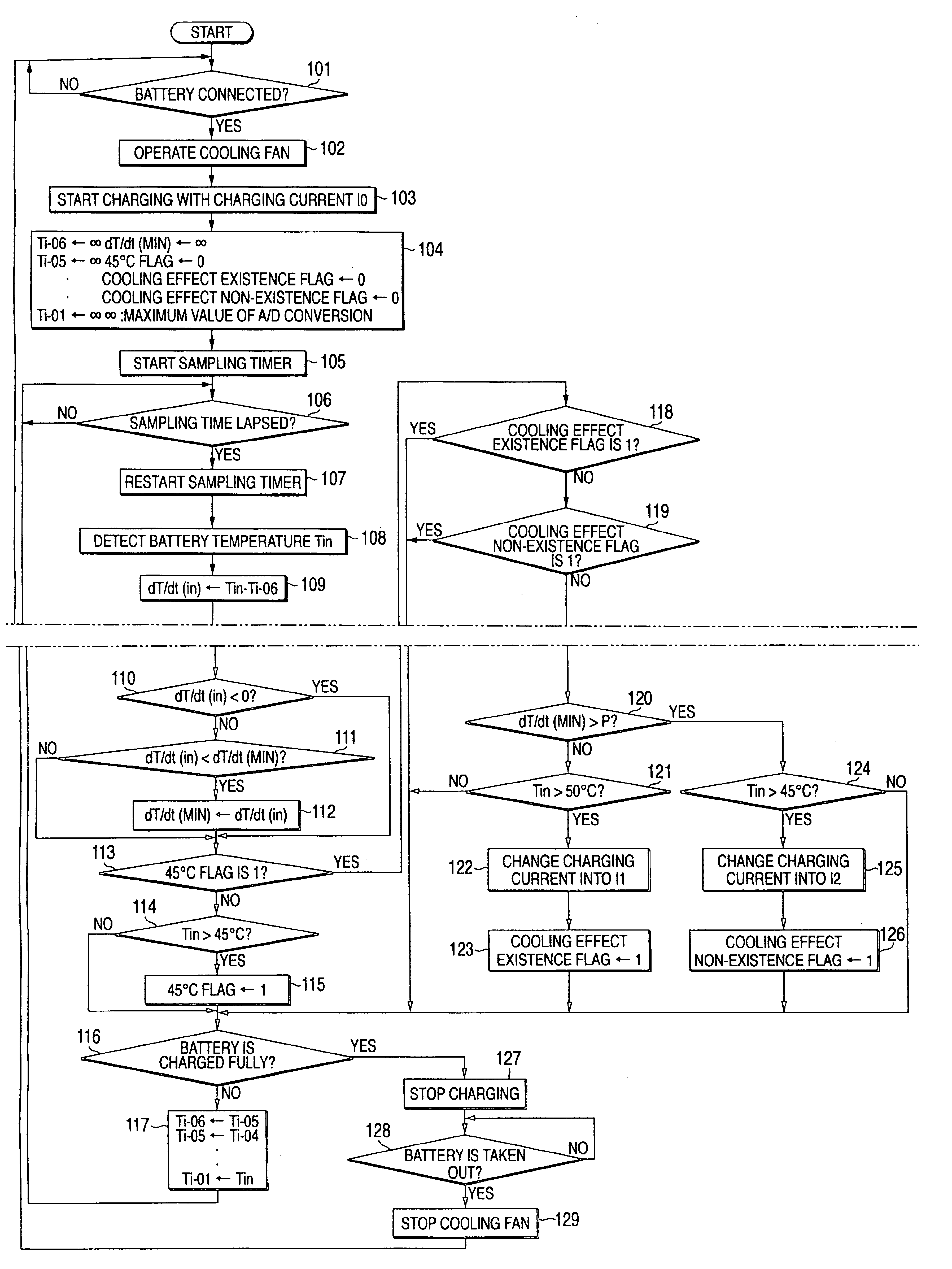
[0015]To achieve the object, the invention provides a charging apparatus, including: a cooling fan for cooling a battery pack; a battery temperature detecting unit configured to detect a battery temperature of the battery pack; and a control unit configured to determine presence or non-presence of cooling effect, to determine full charge of the battery and to control a charging current based on an output of the battery temperature detecting unit; wherein, when the control unit determines that there is no cooling effect by the cooling fan and the battery temperature reaches a first predetermined value smaller than a maximum value of a temperature range in which the battery is chargeable without making a life time thereof shorter, the control unit changes the charging current to a first charging current value where increase of the battery temperature due to charging is suppressed; and wherein, when the control unit determines that there is cooling effect by the cooling fan and the battery temperature reaches a second predetermined value higher than the first predetermined value, the control unit changes the charging current to a second charging current value larger than the first charging current value.
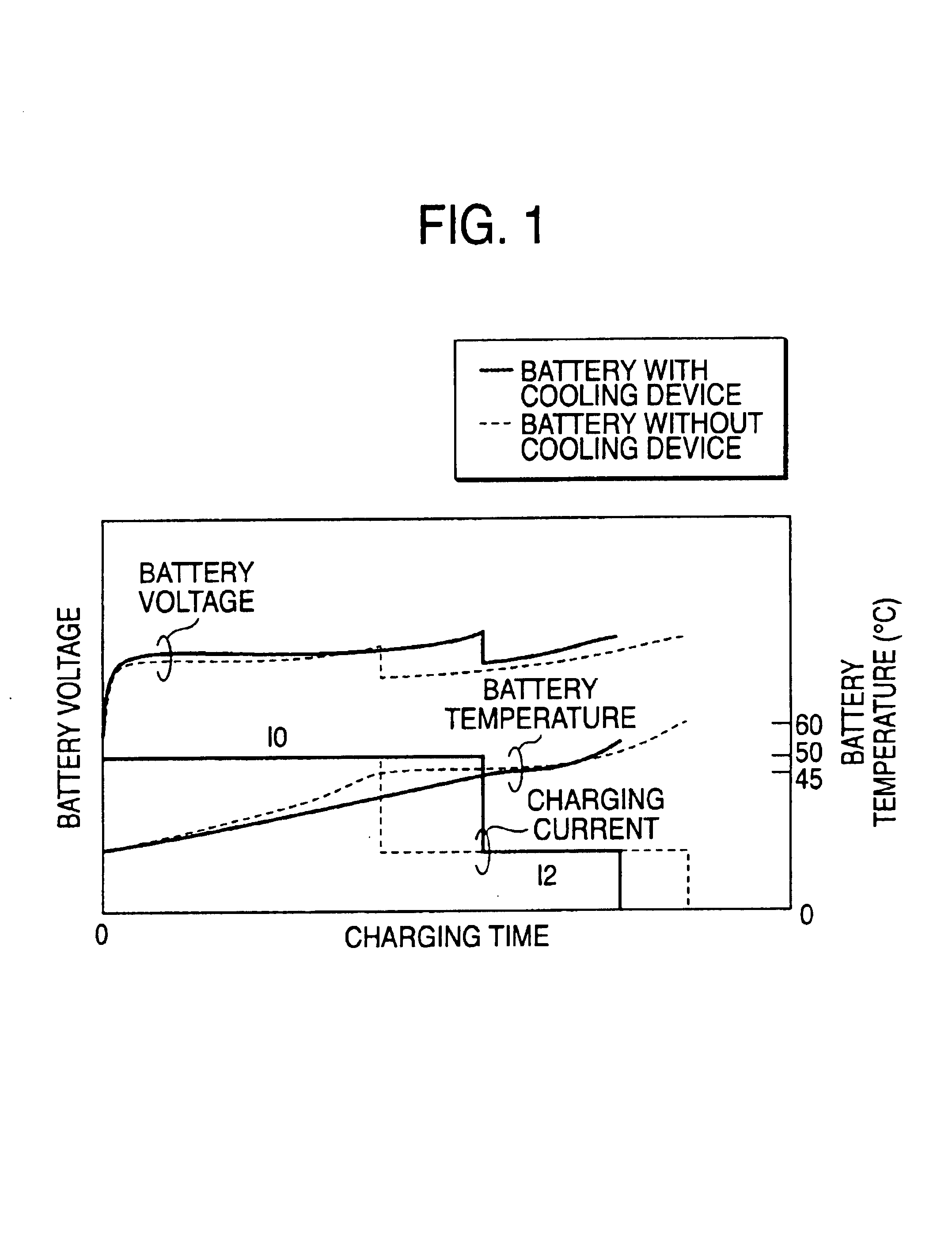
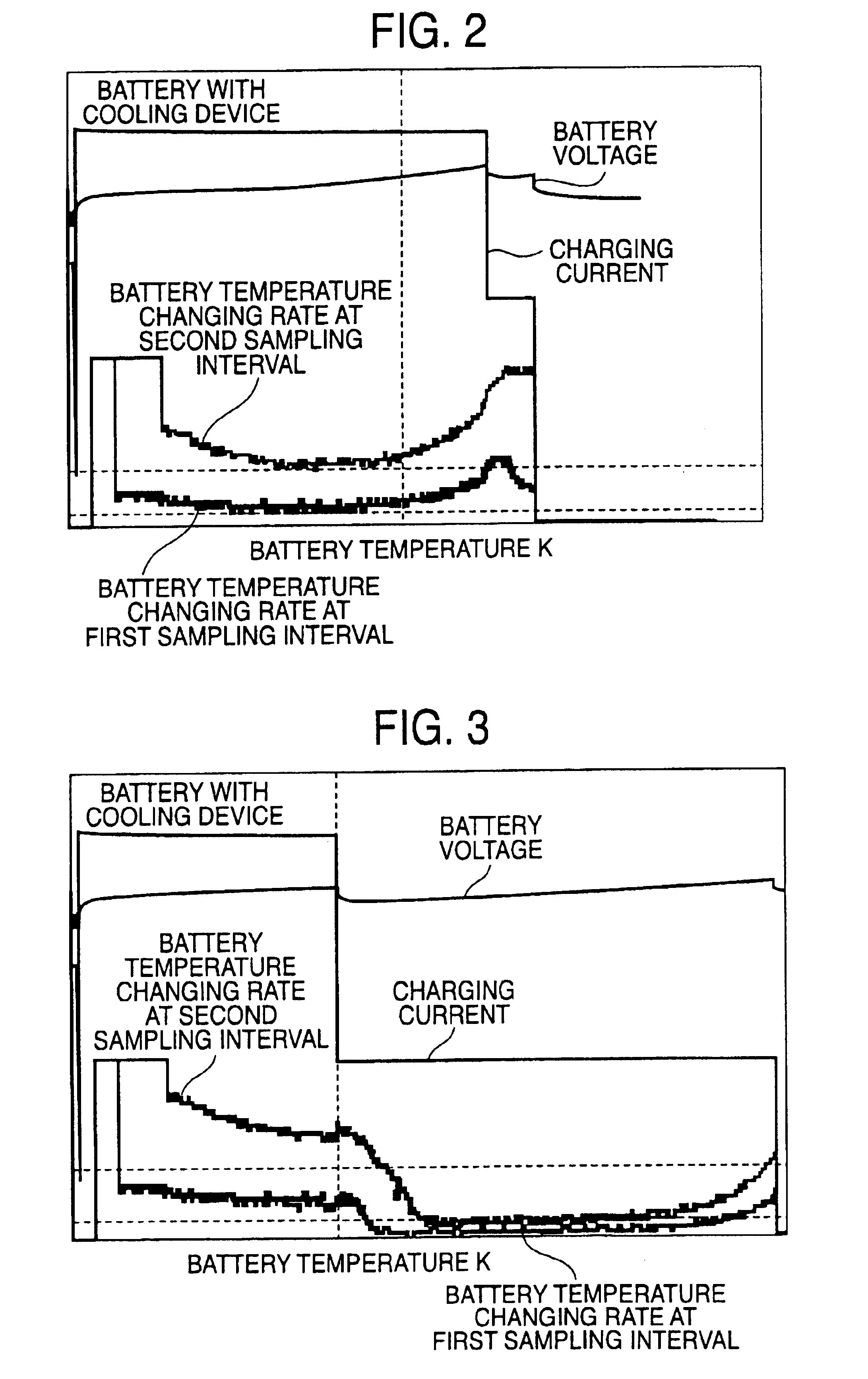
[0016]The invention may be arranged in a manner that a battery temperature changing rate is calculated by using a first sampling interval and a seco

Problems solved by technology

In the case of charging a battery pack such as a nickel cadmium battery or a nickel hydrogen battery used as a power source for a cordless tool etc., although the battery pack can be charged in a short time when charged with a large current, an amount of heat generated from the battery within the battery pack during charge becomes large and so the cycle life of the battery becomes shorter.
However, according to the charging method which selects the average charging current depending on the non-existence or existence of the cooling effect, there arises a problem that the cooling ability is not brought to the maximum and so the charging time can not be made shorter even for the battery pack a the cooling device.
However, since the charging time with the charging current I2 is long, the battery pack with a cooling device does not fully use the cooling ability thereof.
Further, it is unreasonable to determine the presence or non-presence of cooling effect by simply using the battery temperatu

Method used


Image

  • Charging apparatus
  • Charging apparatus
  • Charging apparatus

Examples


first embodiment

[0035]FIG. 4 is a circuit block diagram showing the invention. In the figure, 1 depicts an AC power supply, and 2 depicts a battery pack provided with a battery set 2A formed by a plurality of battery cells connected in series and a temperature detecting element 2B such as a thermistor which is made in contact with or disposed near the battery set 2A to detect the temperature of the battery. 3 depicts a current detecting unit for detecting a charging current flowing into the battery pack 2, 4 depicts a charge control signal transmitting unit which transmits a signal for controlling the start and stop of the charging current, and 5 depicts a charging current signal transmitting unit for feeding back the signal of the charging current to a PWM control IC 23. Each of the charge control signal transmitting unit 4 and the charging current signal transmitting unit 5 is formed by a photo coupler etc. for example. 6 depicts a cooling fan for cooling the battery pack 2, and 7 depicts a drivi...

second embodiment

[0055]FIG. 7 is a circuit block diagram showing a charging apparatus according to the invention.

[0056]In this second embodiment, elements common with those of the first embodiment will be referred by the same references and the explanations for the common elements will be omitted.

[0057]The configurations shown in FIG. 7 are broadly the same as those of the first embodiment shown in FIG. 4, but different in the configuration of the microcomputer 50. The microcomputer 50 is formed by a calculation unit (CPU) 51, a ROM 52, a RAM 53′, a timer 54, an A / D converter 55, output ports 56a, 56b, and a reset input port 57. The CPU 51 calculates a plurality of battery temperature changing rates at every predetermined time period based on a newest battery temperature and a battery temperature sampled before plural sampling time periods, and compares a current battery temperature changing rate with a minimum battery temperature changing rate stored in the RAM 53′. The RAM 53′ contains therein a b...


PUM


Abstract

A charging apparatus includes a cooling fan; a battery temperature detecting unit; and a control unit configured to determine presence or non-presence of cooling effect by the cooling fan, and to control a charging current based on an output of the battery temperature detecting unit. When there is no cooling effect and the battery temperature reaches a first predetermined value smaller than a maximum value of a temperature range in which a battery is chargeable without making a life time thereof shorter, the control unit changes the charging current to a first charging current value where increase of the battery temperature can be suppressed. When there is cooling effect and the battery temperature reaches a second predetermined value higher than the first predetermined value, the control unit changes the charging current to a second charging current value larger than the first charging current value.

Description

BACKGROUND OF THE INVENTION[0001]1. Field of the Invention[0002]The present invention relates to a charging apparatus for charging secondary batteries such as nickel cadmium batteries, and nickel hydrogen batteries.[0003]2. Background Art[0004]In the case of charging a battery pack such as a nickel cadmium battery or a nickel hydrogen battery used as a power source for a cordless tool etc., although the battery pack can be charged in a short time when charged with a large current, an amount of heat generated from the battery within the battery pack during charge becomes large and so the cycle life of the battery becomes shorter. Thus, a charging apparatus is proposed that charges a battery pack with a small charging current for a long time in order to suppress the heat amount of the battery.[0005]On the other hand, another charging apparatus is proposed that charges a battery pack with a large charging current while cooling the battery pack by a cooling fan provided at a charging ap...

Claims


Application Information

Patent Timeline
IPC IPC(8): H02J7/04H02J7/02
CPCH02J7/047H02J7/022H02J7/007194H02J7/02H02J2207/20H02J7/04H02J7/007192
Inventor ARADACHI, TAKAOTAKANO, NOBUHIRO
Owner HITACHI KOKI CO LTD
Why Eureka
Try Eureka