Plasma treatment of anodic oxides for electrolytic capacitors

a technology of dielectric oxide and electrolytic capacitor, which is applied in the manufacture of capacitors, capacitor dielectric layers, variable capacitors, etc., can solve the problems of affecting the dc leakage adversely affecting the dc leakage and stability of the oxide layer, and undesirable for a capacitor to experience high dc leakage and oxide degradation, so as to reduce the dc leakage of the capacitor, improve the electrical properties of the dielectric layer, and reduce the d

Inactive Publication Date: 2007-10-23
WILSON GREATBATCH LTD
View PDF15 Cites 16 Cited by
  • Summary
  • Abstract
  • Description
  • Claims
  • Application Information

AI Technical Summary

Benefits of technology

[0016]In that respect, the purpose of the present invention is to improve the electrical properties of the dielectric layer, particularly for a tantalum anode provided with a dielectric of tantalum oxide by an anodizing process. In a broader sense, however, the present plasma treatment (conventional and high density plasma) process is useful in reducing defects in dielectric oxides in comparison to conventional treatment processes, regardless the process by which the oxide was formed. This, in turn, reduces capacitor DC leakage, increases capacitor charge / discharge energy efficiency, and improves long-term capacitor performance stability. These properties are critical for applications such as in an implantable cardioverter defibrillator where short charging time, high capacitor charge / discharge energy efficiency, and stable lifetime performance are strongly desired.

Problems solved by technology

Nonetheless, the formed oxide often contains defects due to oxygen vacancies and incorporated harmful species from the anodizing electrolytes.
These adversely affect DC leakage and stability of the oxide layer.
It is undesirable for a capacitor to experience high DC leakage and oxide degradation for several reasons.
For one, dielectric oxide degradation results in increased capacitor charging time, which is especially important when the capacitor is incorporated into an implantable medical device.
This is an abnormally rapid heartbeat that if left uncorrected can be fatal.
But, oxide degradation results in increased capacitor charge time.
Oxide degradation also decreases capacitor charge / discharge energy efficiency, which either decreases the useful life of the battery or increases battery and device volume.
All these consequences are a result of defects in the anodic oxide film.
The more imperfect the dielectric oxide, the longer the charge time is and the less efficient the charging and discharging.
Energy needed to reform the valve metal anode decreases the useful life of the battery and, consequently, the implantable defibrillator.
The comparison reveals that HDP N2O annealing has the lowest leakage current and superior time-dependent dielectric breakdown (TDDB) reliability.” The problem is that oxide films deposited by chemical vapor deposition techniques as well as by physical vapor deposition (PVD) have poor stoichiometry and normally contain significant contamination.
Defects in tantalum oxide films that cause high DC leakage and oxide degradation are believed to be mostly due to oxygen vacancies that increase in density as the film thickness increases.
While these conventional heat treatment methods give satisfactory results, they are not believed to completely rid the dielectric oxide of defects, especially those in relatively thick anodic oxides.

Method used


Image

  • Plasma treatment of anodic oxides for electrolytic capacitors
  • Plasma treatment of anodic oxides for electrolytic capacitors

Examples


example i

[0027]A plurality of pressed powder tantalum pellets served as test bodies. They were sintered tantalum powder pellets having an anodically formed tantalum oxide layer about 0.43 μm thick. The pellets are of the type incorporated into tantalum electrolytic capacitors commercially available from Wilson Greatbatch Technologies, Inc., the assignee of this invention.

[0028]Plasma treatment was done in a high-density oxygen plasma chamber. Inductive coupling at 380 kHz RF and 2500 W power supply generated the high-density plasma. The oxygen plasma chamber was maintained at about 0.5 to about 50 mTorr with an ion density of about 1011 ion / cm3 to about 1012 ion / cm3. The anodized tantalum bodies were oxygen plasma treated at various substrate temperatures up to 300° C. with the plasma power ranging from about 500 watts to about 1100 watts. Exposure times ranged from about 1 minute to about 10 minutes. Detailed experimental conditions are shown in Table 1.

[0029]After plasma treatment, the tan...

example ii

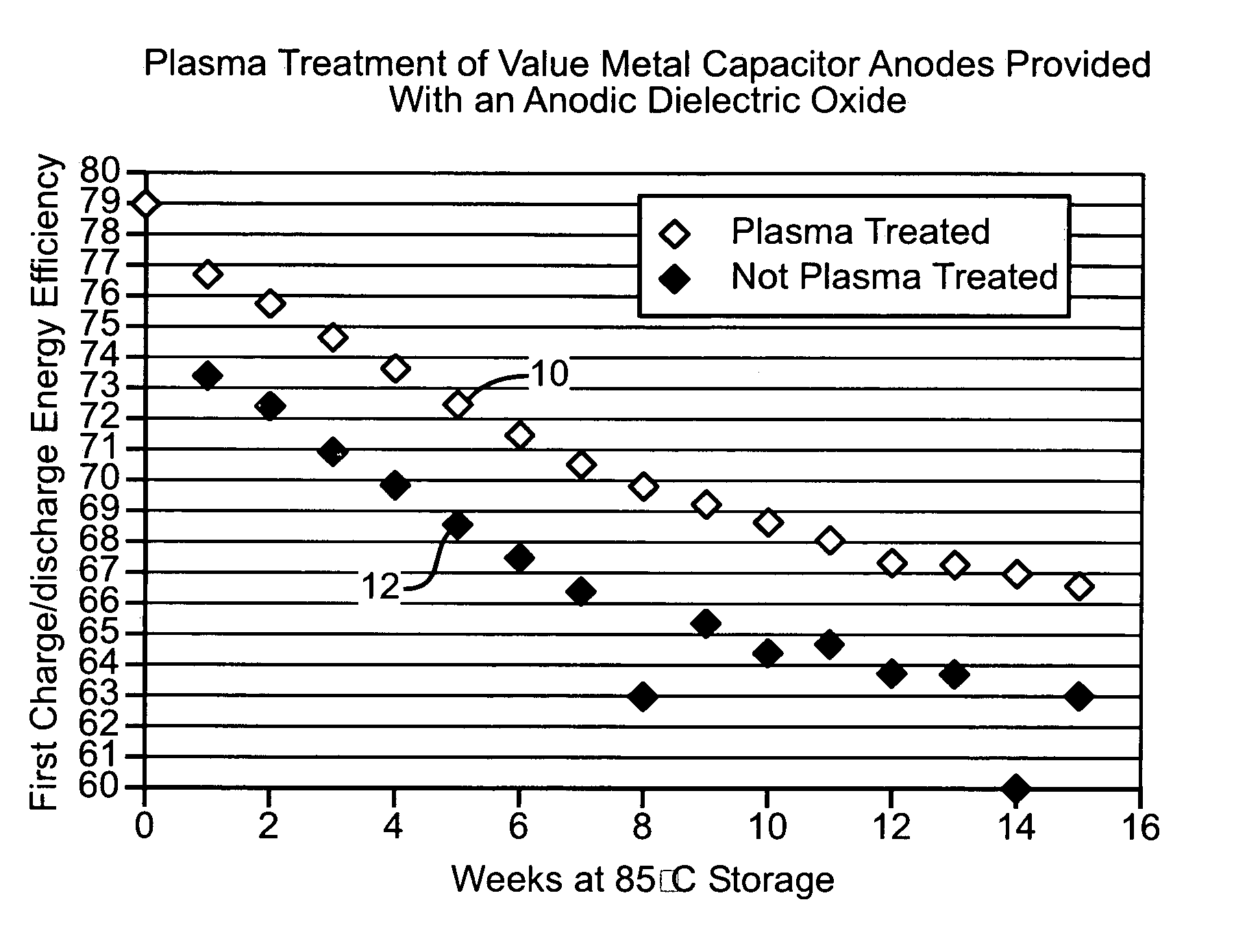
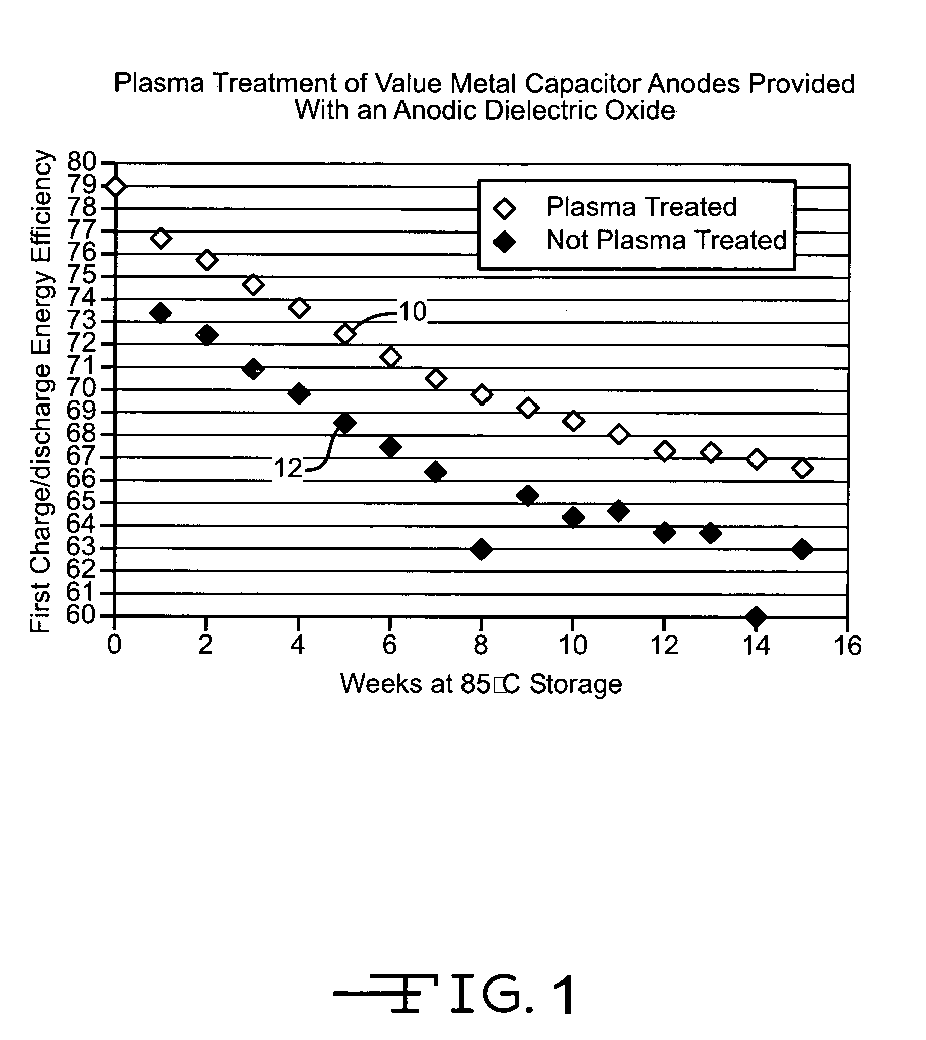
[0035]The capacitors used to create Tables 1 and 2 were further subjected to an accelerated life test. This was done by storing them at 85° C. without bias and then performing a charge / discharge test weekly at 37° C. Charging the individual capacitors at a constant current of 10 mA to the rated voltage of 215 V and subsequently discharging them through a load resistor of about 17 ohms provided the average charge / discharge energy efficiency values shown in FIG. 1. The charge / discharge energy efficiency is the total energy delivered during discharging divided by the total energy put in during charging. The treated anodes were those subjected to O2 plasma having an ion density of about 1011 ion / cm3 to about 1012 ions / cm3 at 500 watts, 203° C. for 4 minutes. This accelerated life test is typically used in evaluating capacitors for implantable cardioverter defibrillators The curve labeled 10 in FIG. 1 was constructed from the capacitors containing the plasma treated anodes while the curv...


PUM

PropertyMeasurementUnit
poweraaaaaaaaaa
thickaaaaaaaaaa
temperatureaaaaaaaaaa

Abstract

An oxygen plasma process for treating a dielectric oxide layer, particularly an anodic oxide, subsequent to its incorporation into an electrolytic capacitor is described. The present treatment reduces DC leakage and improves shelf life stability of the resulting capacitor in comparison to anodic oxides treated in a conventional manner. This is important for critical applications such as implantable cardioverter defibrillators where capacitor charging time and charge / discharge energy efficiency are critical.

Description

CROSS-REFERENCE TO RELATED APPLICATION[0001]This application claims priority to U.S. provisional patent application Ser. No. 60 / 571,042, filed May 14, 2004.BACKGROUND OF THE INVENTION[0002]1. Field of the Invention[0003]The present invention is directed to a plasma process for treating a capacitor dielectric oxide, particularly the anodic oxide serving as the dielectric in an electrolytic capacitor. This treatment reduces the oxygen vacancy defects in the anodic dielectric oxide prior to incorporation of the formed (anodized) anode into the capacitor. Reduced oxygen deficiencies improve the capacitor's DC leakage as well as charge / discharge energy efficiency and long-term performance stability. These properties are important for critical applications such as implantable cardioverter defibrillators.[0004]2. Prior Art[0005]Electrolytic capacitors are well known for use in a variety of electronic equipment such as consumer audio and video equipment, home appliances, power supplies, ind...

Claims


Application Information

Patent Timeline
Patent Type & Authority Patents(United States)
IPC IPC(8): H01G9/04H01G9/00H01G9/042H01G9/052H01G9/07
CPCH01G9/0032H01G9/042H01G9/07H01G9/052Y10T29/417Y10T29/41
Inventor LIU, YANMINGMUFFOLETTO, BARRYGOAD, DAVID
Owner WILSON GREATBATCH LTD
Why Eureka
Try Eureka