Polycrystalline diamond tool for cutting

Inactive Publication Date: 2007-12-06
ONSRUD CUTTER LP
View PDF14 Cites 36 Cited by
  • Summary
  • Abstract
  • Description
  • Claims
  • Application Information

AI Technical Summary

Problems solved by technology

One drawback to HSS is its lack of durability.
Although HSS provides fast feed rates and a high finish quality, tools that contain these materials are not wear-resistant.
Further, the coating decreases the temperature associated with the cutting process, and therefore increases the life of the tool.
However, cutting with carbide can be difficult because carbide is more brittle than

Method used


Image

  • Polycrystalline diamond tool for cutting
  • Polycrystalline diamond tool for cutting

Examples


Embodiment Construction

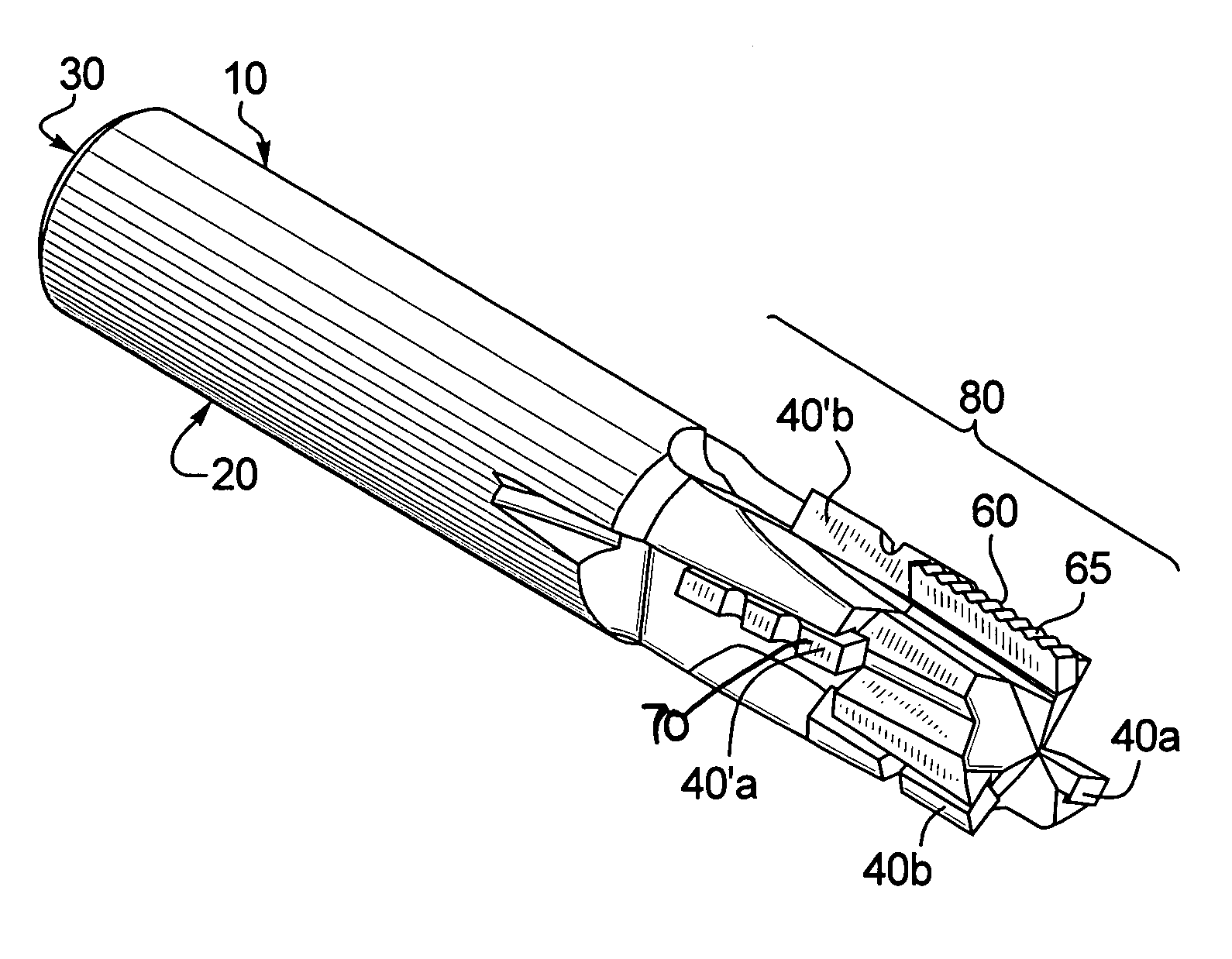
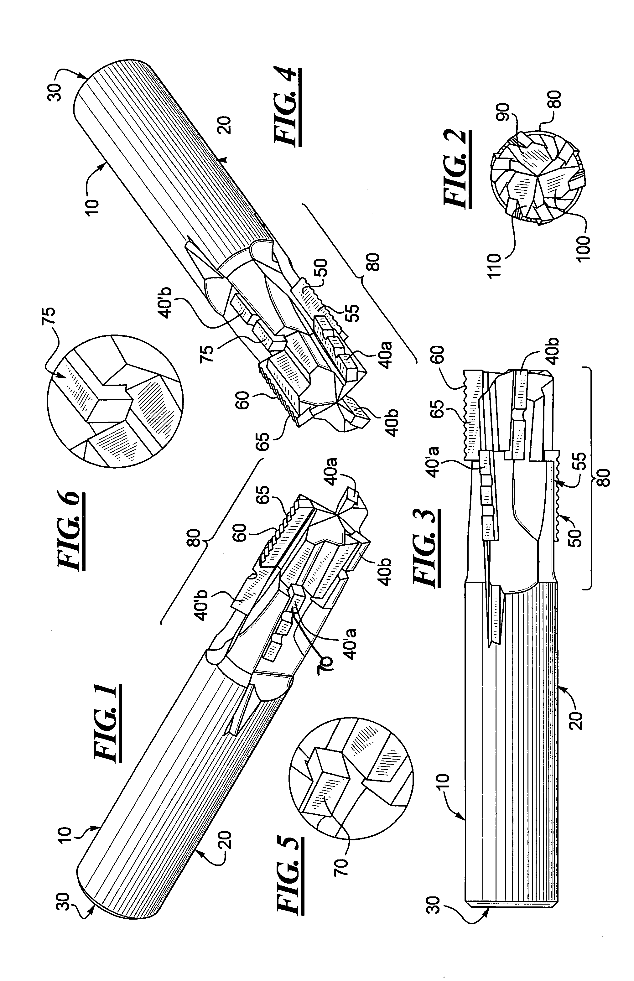
[0018]According to one embodiment of the present invention, a tool for cutting is made of polycrystalline diamond (PCD) that combines rougher, chipbreaker finisher, and compression geometries into one tool. The tool, for example, is a three flute cutter having three upshear flutes and three downshear flutes. The upshear and downshear flutes each possess one rougher wing, which reduces cutting forces, allowing the tool to achieve a higher feed rate, and the two chipbreaker finisher wings create a smooth edge finish. By combining these cutting geometries, the tool of this embodiment is formed that can feed faster than any PCD tool currently on the market while producing a clean edge finish.

[0019]As shown in FIG. 1, a compression tool 10 has a body 20 in the shape of a round shaft. However, other shapes could be used to form the body of the tool 10, including, but not limited to, rectangular or other angular shapes. The body 20 of the tool 10 can have varying widths, depending on the s...


PUM


Abstract

A tool has a shaft and a tip on the shaft. The tip supports rougher and chipbreaker finisher wings which, for example, may be polycrystalline diamond wings. Also, the rougher and chipbreaker finisher wings may be arranged, for example, to provide either upshear or downshear forces. As another example, both upshear and downshear rougher and chipbreaker finisher wings may be arranged to produce corresponding upshear and downshear forces.

Description

BACKGROUND OF THE INVENTION[0001]1. Field of the Invention[0002]The present invention according to one embodiment relates generally to a tool for cutting made of polycrystalline diamond. The present invention according to a different embodiment relates generally to a system for cutting made of upshear and downshear forces.[0003]2. Description of the Related Art[0004]Tools for cutting used in industrial milling applications are known as endmills. A broad category of end milling tools exist, such as flat bottom, ball nose, radius, inverted radius, and chamfer tools. Each category may be further divided by application and geometry. Traditionally, endmills have been made from solid carbide or high speed steel (HSS).[0005]One drawback to HSS is its lack of durability. Although HSS provides fast feed rates and a high finish quality, tools that contain these materials are not wear-resistant. Thus, HSS must be replaced on a regular basis.[0006]As a result, there is a need for a cutting tool...

Claims


Application Information

Patent Timeline
IPC IPC(8): B23C5/10
CPCB23C5/10B23C2210/086B23C2210/205B23C2210/486Y10T407/1946B23C2220/605B23C2226/315B23C2260/80B23C2226/27B23C2210/54
Inventor KOCHAN, WILLIAM J.BELEC, JASON A.
Owner ONSRUD CUTTER LP
Why Eureka
Try Eureka