
Burner head for a gas stove

Inactive Publication Date: 2007-12-06
TEST INT COMPANY
View PDF1 Cites 23 Cited by
  • Summary
  • Abstract
  • Description
  • Claims
  • Application Information

AI Technical Summary

Benefits of technology

[0005]One objective of the present invention is to provide a burner head for a gas stove, which can provide even-burning fire flames and is more safety.
[0011]The present invention has advantages as follows: 1. The gas-exiting grooves of the present invention are disposed in tilt so that the burning fire becomes rotating flames and the even-burning effect can be attained. 2. The rotating flames formed from the tilt gas-exiting grooves of the present invention can sufficiently burn the oxygen in the air. It is not only that the gas is burned sufficiently to increase the utility efficiency of gas but also that amounts of carbon monoxide owing to insufficient burning is decreased, and improving the safety. 3. The gas-exiting grooves of the present invention provide more stable burning than the conventional holes structure. The influence of taken-in air flow is small, and it overcomes the problem that the fire jumps away from the burner head due to the too high air flow rate, and hence the safety of the gas stove is improved.

Problems solved by technology

However, gas is transported via the holes, and it may result in the fire jumps away from the burner head due to excessive adjustment of air mixed with the gas.
As a consequence, the burning can not be kept steady.
In addition, the burning maybe incomplete due to insufficient amount of the mixed air, and it even may cause excessive carbon monoxide to increase the risk of poisoning the user.

Method used


Image

  • Burner head for a gas stove
  • Burner head for a gas stove
  • Burner head for a gas stove

Examples


Embodiment Construction

[0017]In order to describe the structure and characteristics of the present invention in detail, a preferred embodiment accompanying with drawings is explained in the following.

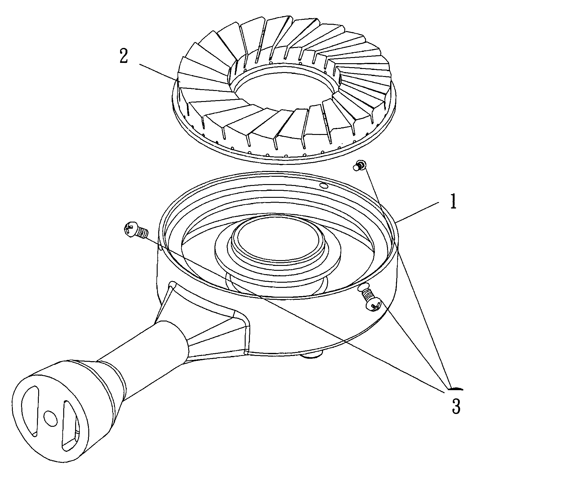
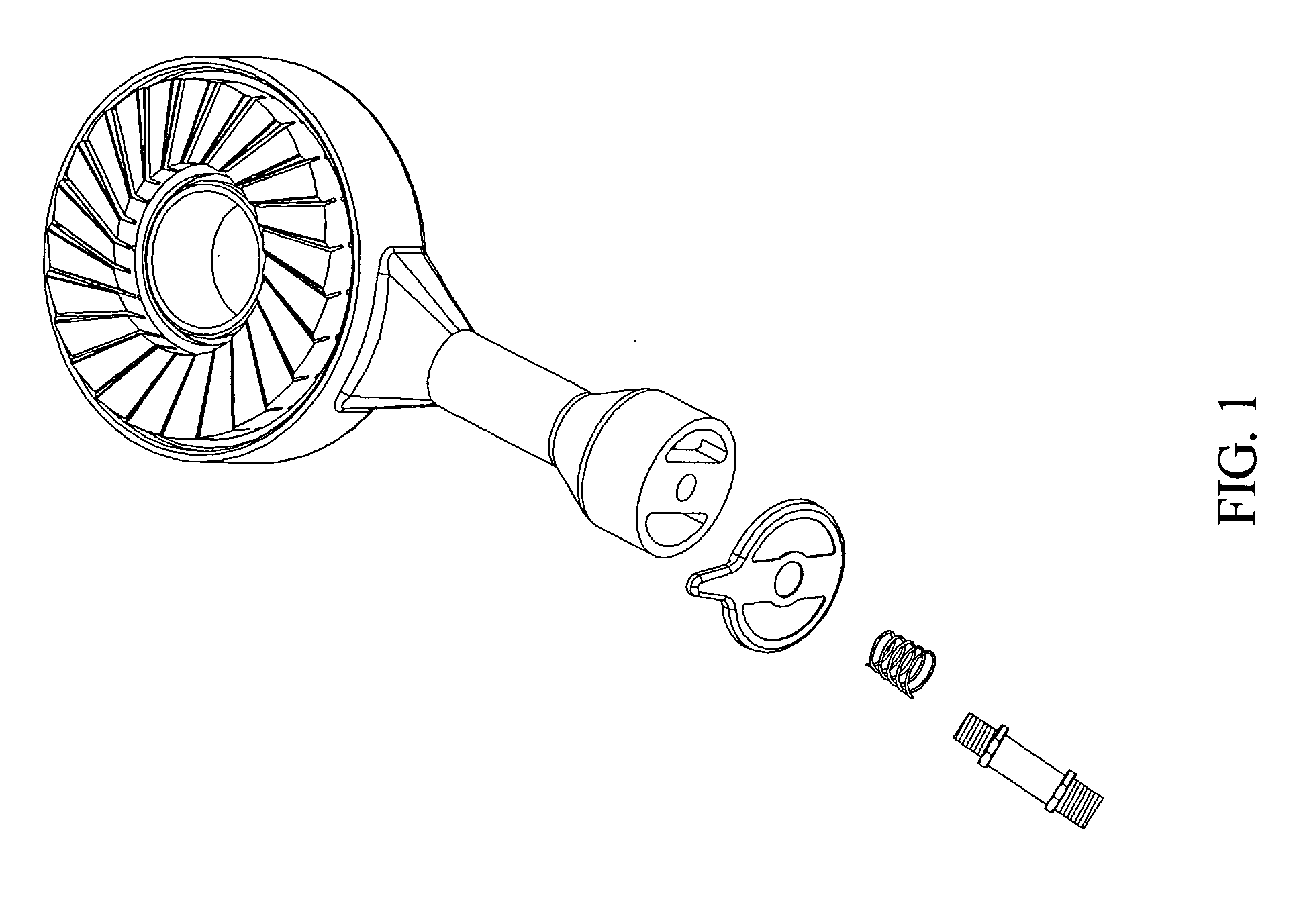
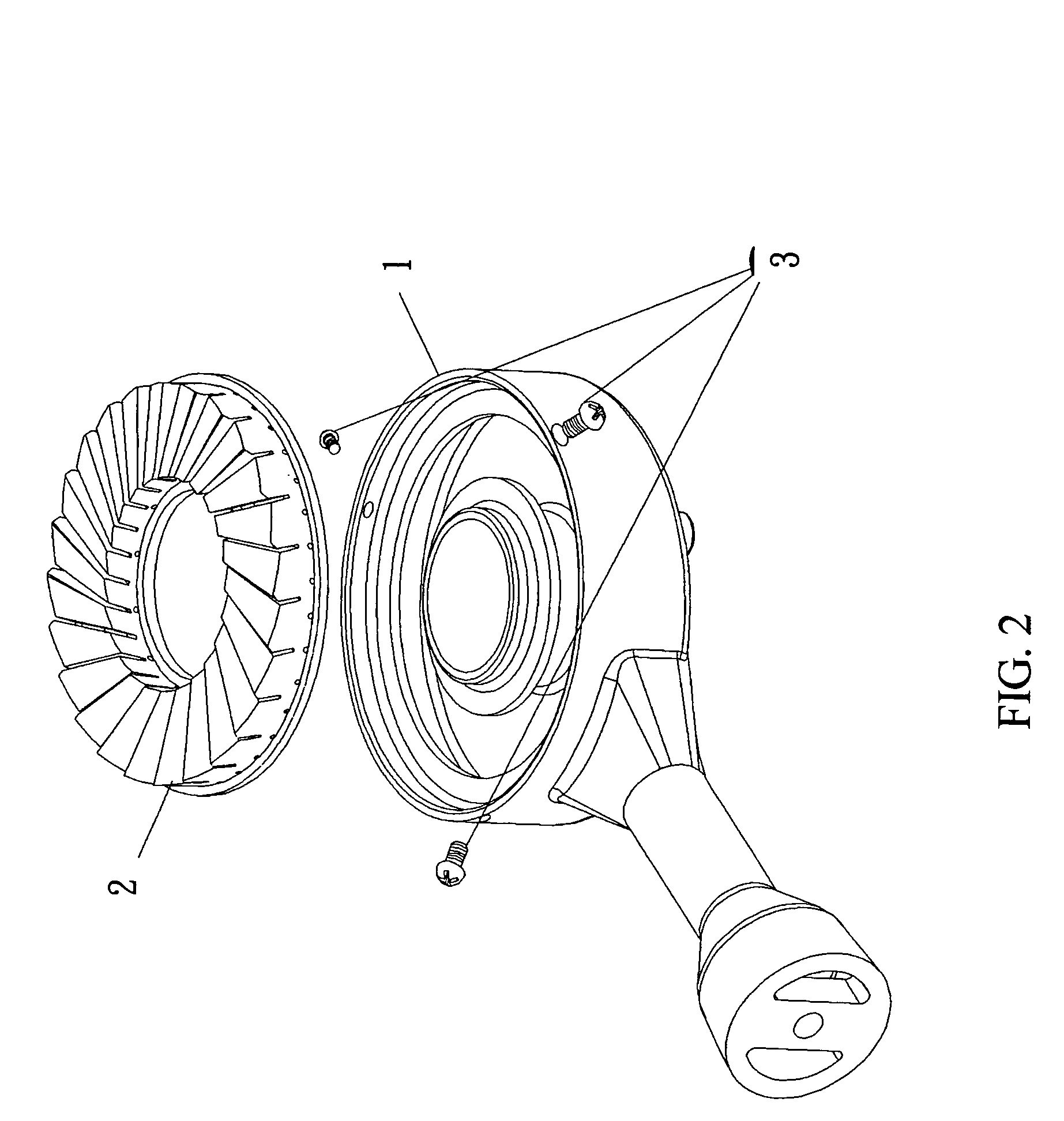
[0018]As FIG. 1 through FIG. 4 shows, the burner head 1 of the present invention includes a base 10 and an annular cover 20 in which a circle of small holes 21 through inner and outer surroundings of the annular cover 20 formed on the lower portion of the annular cover 20, and a plurality of gas-exiting grooves 22 through the inner and outer surroundings of the annular cover 20 disposed on the upper portion of the annular cover 20. The gas-exiting grooves 22 are not disposed in radial directions from the center of annular cover 20 but are disposed in a way that a predetermined angle a is contained between the adjacent gas-existing grooves 22. As such, the rotating flame can be formed to attain the even-burning effect, and it can sufficiently burn the oxygen in the air. It is not only that the gas is burned su...


PUM


Abstract

This invention provides a burner head for a gas stove that can provide even-burning fire flames and is more safety. The burner head for a gas stove comprises a base and an annular cover, which is characterized in that small holes through inner and outer surroundings of the annular cover are disposed at a lower portion of the annular cover and gas-exiting grooves through the inner and outer surroundings of the annular cover are disposed at an upper portion of the annular cover.

Description

BACKGROUND OF THE INVENTION[0001]1. Field of the Invention[0002]The present invention relates to a burner head for a gas stove.[0003]2. Description of the Related Art[0004]A burner head of a conventional gas stove used by people at home comprises a base with an open upper side, a gas transportation station connected with a gas channel provided at the central location of the base, an annular cover covering the base, wherein a circle of small holes and a circle of big holes are provided at the outer surrounding of the annular cover and a circle of small holes and a circle of big holes are provided at the inner surrounding of the annular cover and a gas exit of the gas transportation station is located on the inner surrounding of the annular cover. The fire is burned beginning from the small holes while burning, and then the fire is burned from the big holes via the small holes to form four annular-shaped even-burning fires. This kind of burner head can provide four annular-shaped even...

Claims


Application Information

Patent Timeline
IPC IPC(8): F23D14/62
CPCF23D14/583F23D14/085
Inventor LI, SHENG-QUN
Owner TEST INT COMPANY
Features
  • Generate Ideas
  • Intellectual Property
  • Life Sciences
  • Materials
  • Tech Scout
  • Unparalleled Data Quality
  • Higher Quality Content
  • 60% Fewer Hallucinations
Learn More