Instrument, imaging position fixing system and position fixing method

Inactive Publication Date: 2007-12-06
SIEMENS AG
View PDF15 Cites 109 Cited by
  • Summary
  • Abstract
  • Description
  • Claims
  • Application Information

AI Technical Summary

Benefits of technology

[0004]The object of the invention is to overcome the disadvantages of the prior art. In particular an instrument is to be provided of which the position in a body can be determined with particular accuracy, with high sensitivity and in a simple mann

Problems solved by technology

A disadvantage of the known method for determining the position is that to the coil system provided for magnetizing the marker is com

Method used


Image

  • Instrument, imaging position fixing system and position fixing method
  • Instrument, imaging position fixing system and position fixing method
  • Instrument, imaging position fixing system and position fixing method

Examples


Embodiment Construction

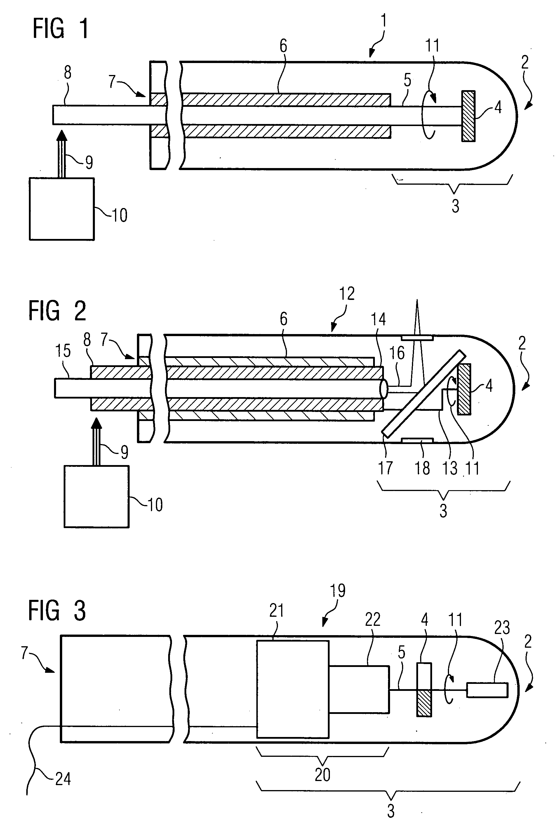
[0053]FIG. 1 shows a schematic, enlarged diagram of a first embodiment of the inventive instrument. The instrument concerned is for example a catheter 1 which can be introduced into the body of a living being, especially of a human being, with a free first end 2 for introduction into the body. There is provision for a magnet 4 in the end section 3 containing the free end 2. The magnet 4 is connected to a shaft 5 provided to transmit a rotational movement to the magnet 4 in such a way that a rotation of the magnet 4 creates an alternating magnetic field suitable for locating the magnet's position. Starting from the end section 3, the shaft 5 which can be rotated in a tube 6, is routed through the catheter 1 to a second end 7. A shaft end 8 is brought out at a second end 7 of the catheter 1. The shaft end 8 can be coupled to a drive unit 10 by means of a schematically depicted clutch 9. A direction of rotation of the magnet 4 is indicated by the reference symbol 11.

[0054]The function ...


PUM


Abstract

The invention relates to an instrument able to be introduced into a body as well as an imaging position fixing system and position fixing method for the instrument. A magnet able to be rotated with a rotation drive is provided in an end section of the instrument. The position of the magnet in the body can be determined on the basis of the strength of a magnetic alternating field created by a rotation of the magnet.

Description

CROSS REFERENCE TO RELATED APPLICATIONS[0001]This application claims priority of German application No. 10 2006 0223 filed May 19, 2006, which is incorporated by reference herein in its entirety.FIELD OF THE INVENTION[0002]The invention relates to an instrument, an imaging position fixing system and an imaging position fixing method for the instrument.BACKGROUND OF THE INVENTION[0003]A marker which can be moved within a hollow cavity of a body of a living being is known from DE 195 32 676 C1. The marker is made from a magnetic material. To determine the position of the marker a pulsed external magnetic field is applied to it from a predetermined direction. To create the magnetic field a coil system is provided. A magnetic remanence field is created by the magnetic field in the marker in the predetermined direction. The strength of the magnetic remanence field is measured in the absence of the external magnetic field by means of magnetic coils. The position of the marker in the body ...

Claims


Application Information

Patent Timeline
IPC IPC(8): A61B5/05A61B8/14
CPCA61B5/06A61B5/062A61B10/02A61B19/5244A61B2019/5454A61B2019/5238A61B2019/5251A61B2019/5276A61B2019/528A61B19/54A61B34/20A61B2090/376A61B2090/3784A61B2034/2051A61B2090/378A61B90/39A61B2090/3954
Inventor BILL, ULRICHHOHEISEL, MARTIN
Owner SIEMENS AG
Why Eureka
Try Eureka