
Feed device intended for mounting in a fuel tank

a technology for feeding devices and fuel tanks, which is applied in the direction of liquid handling, instruments, packaged goods types, etc., can solve the problems of high material consumption, high manufacturing cost of baffles,

Inactive Publication Date: 2002-10-22
MANNESMANN VDO AG
View PDF4 Cites 13 Cited by
  • Summary
  • Abstract
  • Description
  • Claims
  • Application Information

AI Technical Summary

Benefits of technology

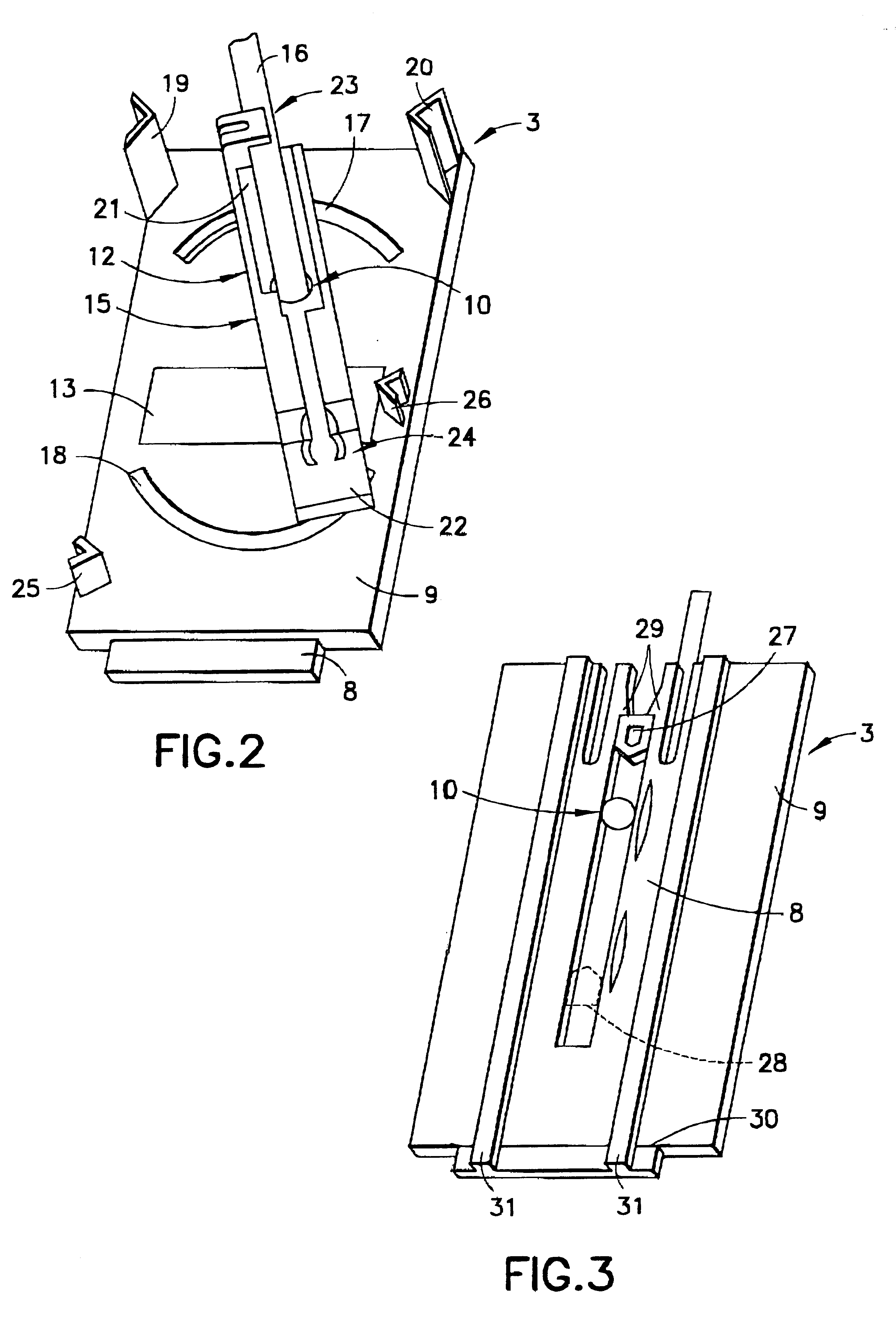
As a result of this design, the orientation of the lever arm mounted on the carrier and the position of the float may be varied by an appropriate orientation of the carrier parts relative to one another. The feed device according to the invention is therefore suitable for use in fuel tanks having a variety of different configurations. The present invention obviates the need for very long and therefore cost-intensive guides. The feed device according to the invention can therefore be manufactured particularly cost-effectively. Moreover, the feed device according to the invention requires only a very small amount of construction space because the carrier may be fastened on the feed unit or on the baffle at a position that is determined irrespective of the fuel tank design. In a simple embodiment, the second carrier part is arranged on the first carrier part so that the second part is offset by a particular angle.
According to another embodiment of the present invention, the yoke is guided with particular accuracy when the carrier possesses tracks which are arranged on mutually opposing regions of the mounting and on which the yoke is supported or guided. Accordingly, as the yoke pivots about the mounting, the radial outer regions of the yoke are guided in the tracks arranged on opposing sides of the mounting. This contributes to increasing the accuracy of the signals from the position sensor.

Problems solved by technology

The baffle is consequently highly cost-intensive to manufacture.
Furthermore, the baffle requires a high and therefore cost-intensive use of material, since the guide has to extend on the baffle over a region far exceeding the length of the carrier.

Method used


Image

  • Feed device intended for mounting in a fuel tank
  • Feed device intended for mounting in a fuel tank
  • Feed device intended for mounting in a fuel tank

Examples


Embodiment Construction

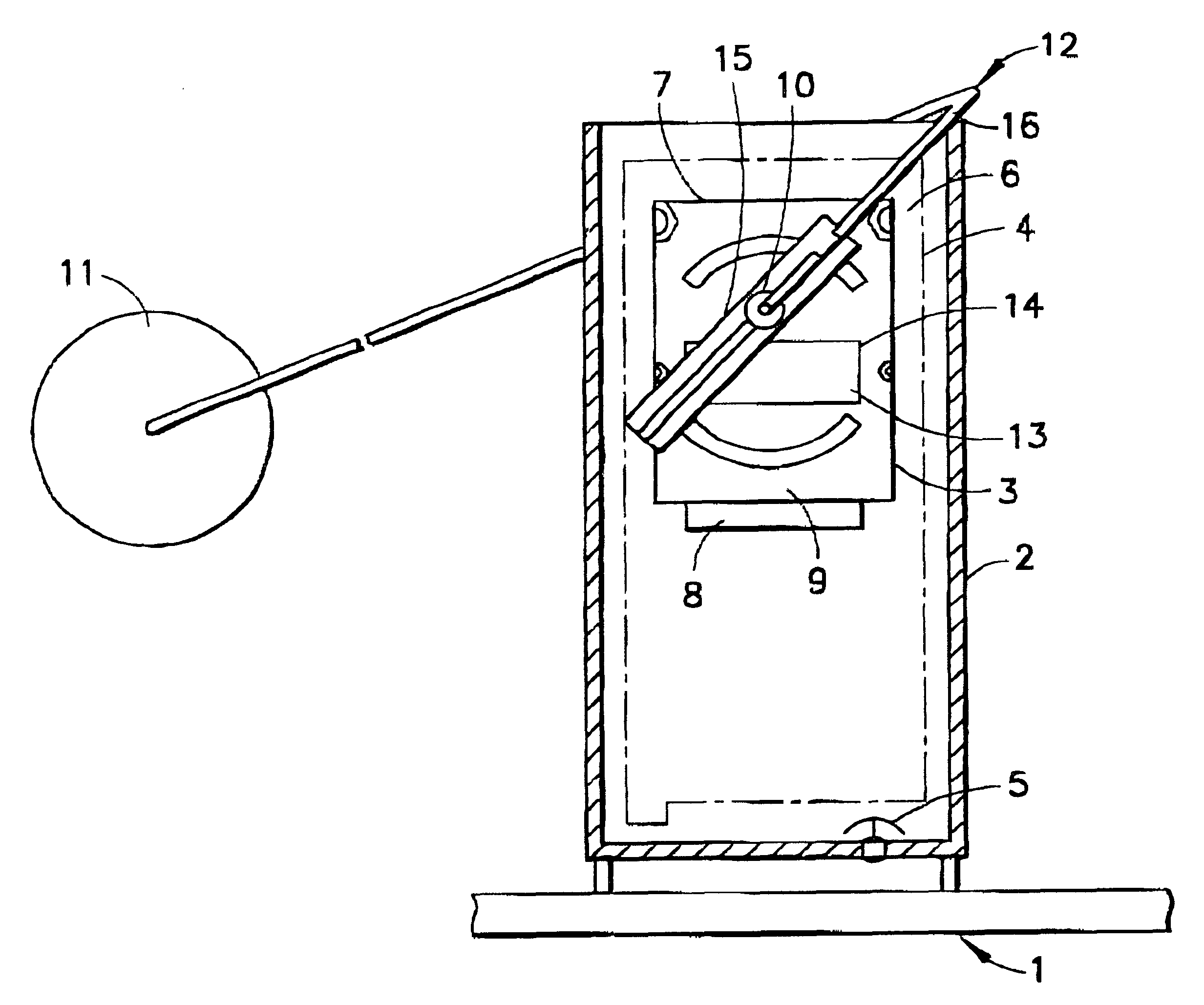
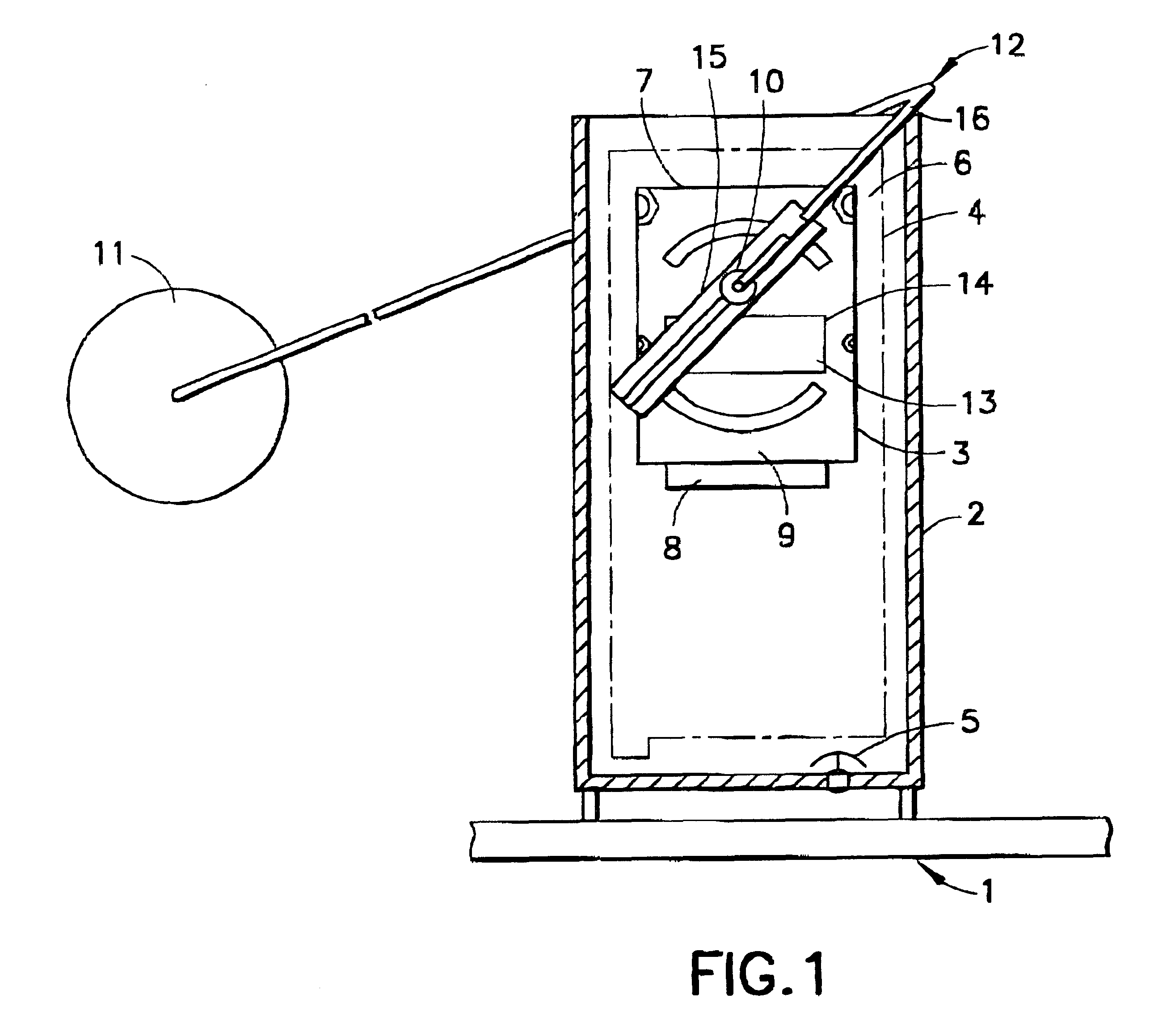
FIG. 1 is a longitudinal sectional view of a baffle 2 arranged in a bottom region of a fuel tank 1. The baffle 2 includes a filling-level sensor 3 and a feed unit 4 indicated by dashes and dots in the drawing. The feed unit 4 feeds fuel out of the baffle 2 to an internal combustion engine which is not illustrated. A bottom valve 5 is arranged in the baffle for filling the baffle 2 with fuel.

The filling-level sensor 3 is fastened to a vertical wall 6 inside the baffle 2 via a carrier 7. The wall 6 may comprise part of the feed unit 4, the baffle 2, or another part of the fuel tank 1. The carrier 7 includes a first carrier part 8 connectable to the wall 6 and a second carrier part 9 positively connected to the first carrier part 8. The second carrier part 9 has a mounting 10 in which a lever arm 12 carrying a float 11 is pivotally received. A resistance slide track 13 of a position sensor 14 designed as a potentiometer is also arranged on the second carrier part 9. As an alternative, ...


PUM

PropertyMeasurementUnit
angleaaaaaaaaaa
heightsaaaaaaaaaa
heightaaaaaaaaaa

Abstract

In a feed device with a filling-level sensor fastened to a wall of a baffle, the filling-level sensor has a lever wire for holding a float. A carrier for mounting the filling-level sensor to a wall of the baffle has a first carrier part connected to the baffle and a second carrier part having the mounting for the lever wire. The pivoting range of the float is set by the selected orientation of the second carrier part on the first carrier part. The feed device is consequently suitable for use in differently constructed fuel tanks.

Description

1. Field of the InventionThe present invention relates to a feed device for installation in a fuel tank having a baffle for collecting fuel, a feed unit for feeding fuel out of the baffle, and a filling-level sensor having a lever arm carrying a float pivotally arranged in a mounting on a carrier arranged on the baffle.2. Description of the Related ArtFeed devices having baffles in which feed units and filling level sensors are arranged are often used in fuel tanks of present-day motor vehicles. The feed units are supported on the bottom of the fuel tank and are designed as a structural unit together with the baffle. The baffle has a guide with a plurality of orifices arranged at different heights. A carrier is arranged in the guide and has a lug for interlocking with one of the orifices. Accordingly, the carrier is connectable to the baffle at different heights thereby allowing standardized components of the feed device to be used in differently constructed fuel tanks which require...

Claims


Application Information

Patent Timeline
Patent Type & Authority Patents(United States)
IPC IPC(8): B60K15/077G01F23/30G01F23/36F02D33/00F02M37/00
CPCB60K15/077F02D33/003G01F23/363B60K2015/03217B60K2015/03453B60K2015/03467F02M37/0082
Inventor KORST, OTTOPANTRING, DETLEF
Owner MANNESMANN VDO AG
Learn More