
Modular system

Active Publication Date: 2018-06-19
KSM CASTINGS GROUP
View PDF37 Cites 7 Cited by
  • Summary
  • Abstract
  • Description
  • Claims
  • Application Information

AI Technical Summary

Benefits of technology

The invention describes a system for creating a load-bearing frame for a motor vehicle by using a single cast structure made of lightweight metal like aluminum. This helps to reduce the weight of the frame and make it easier to assemble. The cast structure has nodes that allow for easy connection between different profiles. This system simplifies the manufacturing process and reduces costs compared to traditional methods.

Problems solved by technology

It is a disadvantage in some of the aforementioned frames or the floor group that they comprise a plurality of individual parts in the rear region of a motor vehicle, which must be joined together on site, in complicated, time-consuming and therefore cost-intensive manner.
It is a further disadvantage that some of the aforementioned frames and the said floor groups are configured in such a manner that they can be connected with chassis components, particularly with wheel suspensions such as steering arms, stabilizers, springs and / or dampers, only by way of a subframe, which is also referred to as an assembly support, axle support or auxiliary frame.
Furthermore, the said frames or floor groups also have a relatively high weight, which has a negative effect on the fuel consumption of a motor vehicle.
Furthermore, the said frames or floor groups, which have many connection points or joining locations, are more susceptible to production defects and can also have reduced mechanical properties with regard to a desired deformation behavior or a desired rigidity.
Frames or floor groups as mentioned above are known to be complicated in their development and are generally tailored to a single vehicle type or a single vehicle series.
A disadvantage of this is that individual parts that already exist often can no longer be used for a new vehicle type or a new vehicle series, and, in particular, the machines specifically procured and generally newly developed for their production can no longer be used, and therefore have to be newly procured or, if necessary, newly developed.

Method used


Image

  • Modular system
  • Modular system
  • Modular system

Examples


Embodiment Construction

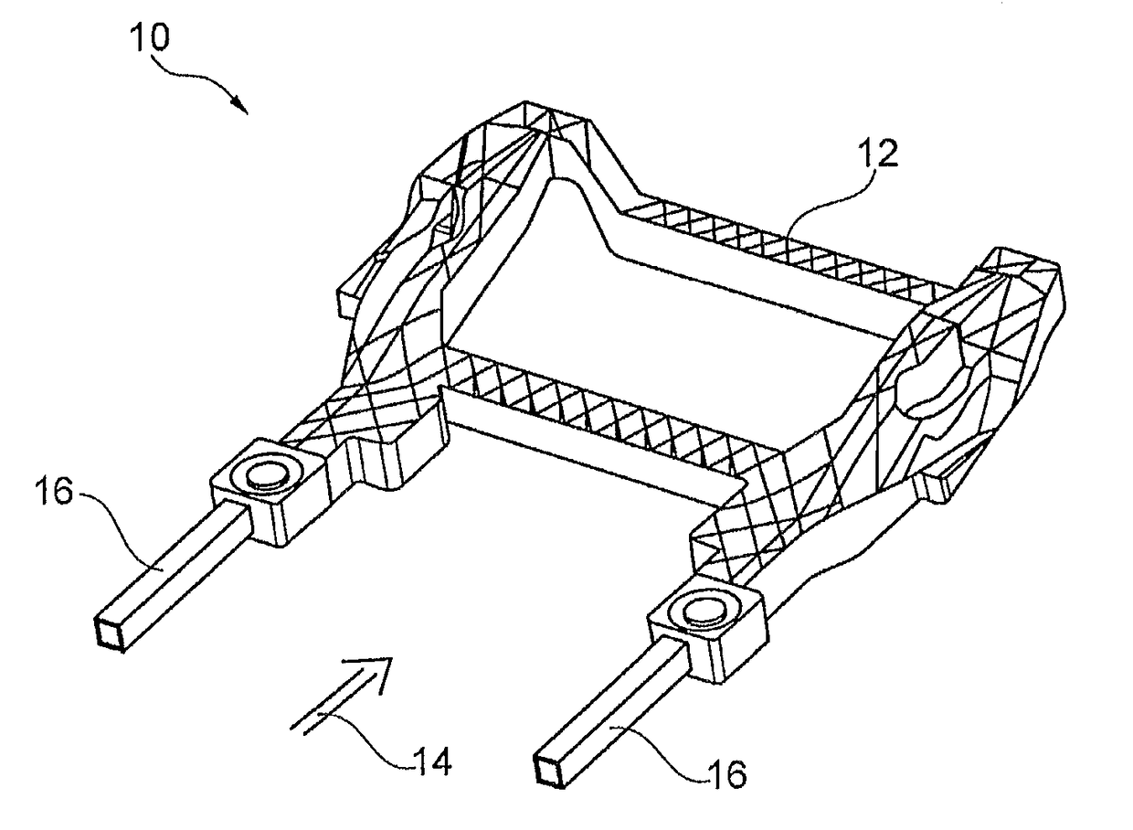
[0057]FIG. 1 shows a load-bearing frame to be disposed in a rear region of a motor vehicle, built up of components of a modular system 10 according to the invention. In the exemplary embodiment shown, the major portion of the frame is formed by a single cast structure 12, which comprises all the nodes and cross members. On the rear side of the cast structure 12, seen in the direction of travel 14, a profile 16, particularly an extruded profile in the form of a side member, is disposed on each side of the cast structure 12.

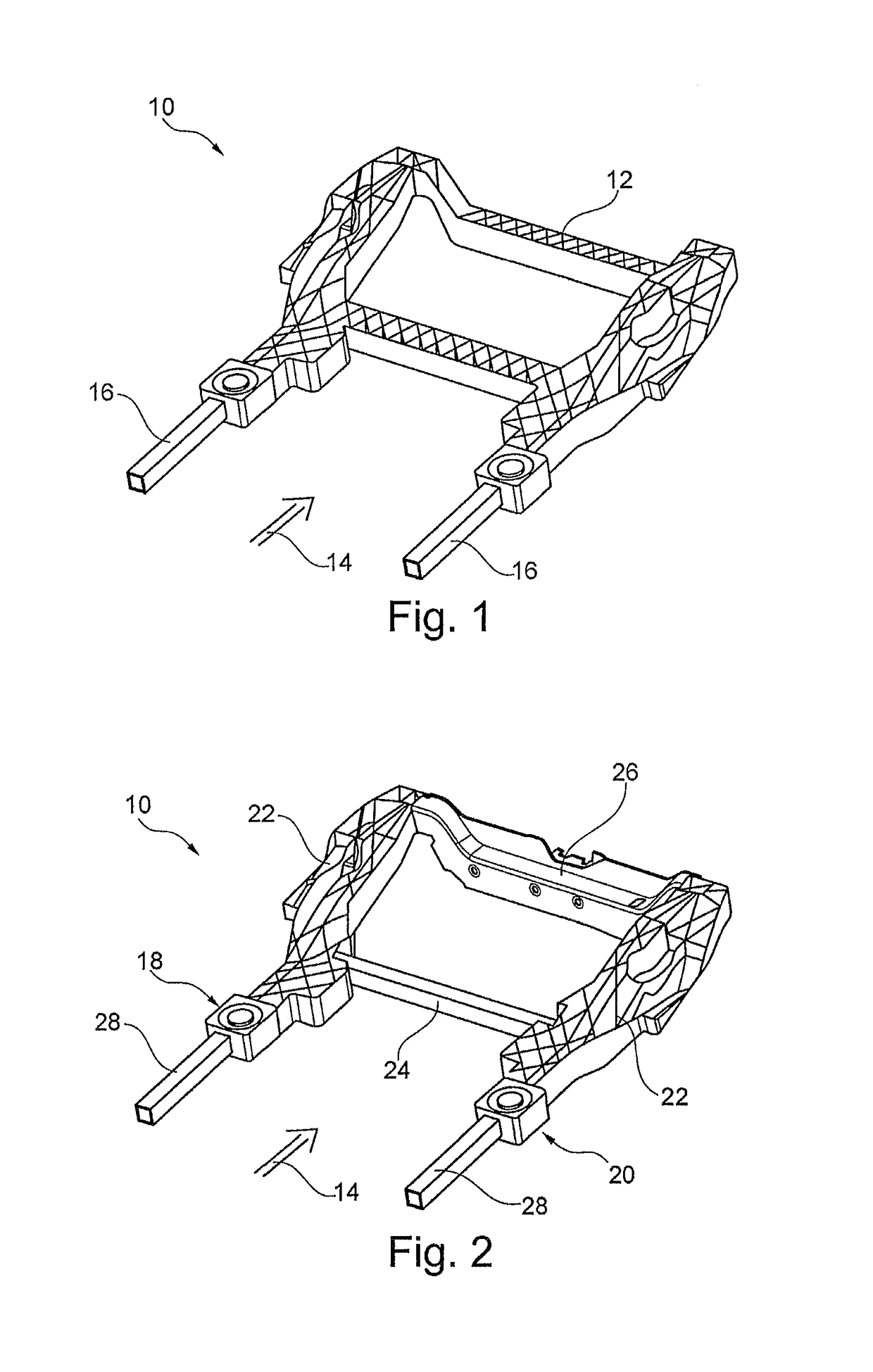
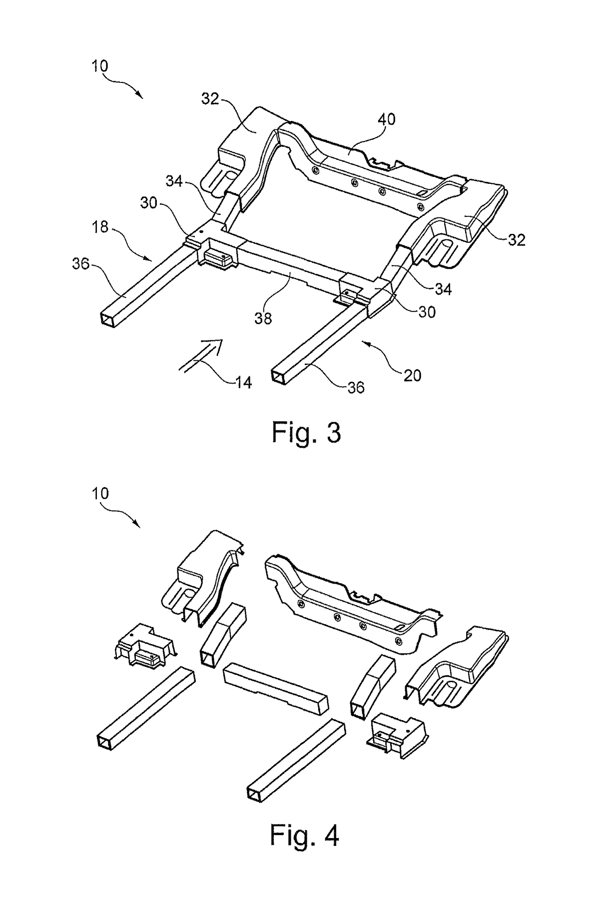
[0058]FIG. 2 shows a load-bearing frame to be disposed in the rear region of a motor vehicle, built up from components of a modular system 10 according to the invention. In the exemplary embodiment shown, the left side 18 and right side 20 of the frame, viewed in the direction of travel 14, are formed, for the most part, from a cast structure 22, in each instance, wherein the respective cast structure 22 comprises all the nodes of its frame side 18, 20. The cast st...


PUM


Abstract

A modular system in the form of a load-bearing frame to be arranged in a tail region of a motor vehicle. The modular components which are to be linked or are linked include at least one cast structure and at least two profiles, the cast structure comprising at least one node.

Description

CROSS REFERENCE TO RELATED APPLICATIONS[0001]This application is the National Stage of PCT / DE2013 / 100367 filed on Oct. 24, 2013, which claims priority under 35 U.S.C. § 119 of German Application No. 10 2012 110 176.0 filed on Oct. 24, 2012, the disclosure of which is incorporated by reference. The international application under PCT article 21(2) was not published in English.BACKGROUND OF THE INVENTION[0002]1. Field of the Invention[0003]The invention relates to a modular system as a load-bearing frame to be disposed in the rear region of a motor vehicle.[0004]2. Description of the Related Art[0005]It is known that in the automotive industry, frames are used as a load-bearing lower framework for the motor vehicle superstructure. Such frames essentially form the main framework of the motor vehicle. Usually, the wheel suspension and the assemblies of the motor vehicle are attached to this frame. Known frames consist of two side members that are welded, riveted or screwed onto cross me...

Claims


Application Information

Patent Timeline
IPC IPC(8): B62D21/08B62D29/00B62D25/20B62D21/02
CPCB62D21/08B62D21/02B62D25/2027B62D29/008
Inventor BUSCHJOHANN, THOMASLACHMUND, HEIKROETH, THILOKERN, DANIEL
Owner KSM CASTINGS GROUP
Learn More