
Self-protecting device for an object

a self-protection device and object technology, applied in the direction of measurement devices, direction controllers, instruments, etc., can solve the problems of search radar for vectoring of target tracking radar, a considerable level of development complication and expenditure, and relatively high cost of search radar in respect of its procuremen

Inactive Publication Date: 2007-06-26
DIEHL BGT DEFENCE GMBH & CO KG
View PDF8 Cites 8 Cited by
  • Summary
  • Abstract
  • Description
  • Claims
  • Application Information

AI Technical Summary

Benefits of technology

[0005]Therefore the object of the present invention is to provide an object self-protection apparatus of the kind set forth in the opening part of this specification in which a relatively cost-intensive search radar as a monitoring device which is fixed with respect to the object is eliminated, without adversely affecting the self-protection properties.
[0007]In the object self-protection apparatus according to the invention the monitoring device which is fixed with respect to the object is not formed by a relatively cost-intensive monitoring radar with individual radiating devices arranged in at least one vertically oriented group, but by a passive sensor device which is provided for angle detection of the missile which is approaching and which is to be defended against. The passive sensor device which can be formed by an image-producing and -processing UV sensor device or by an image-producing and -processing IR sensor device also serves for sensor fusion with a simple radar missile warner for clear close range detection, whereby for example false alarms are avoided. Consequently in the event of a threat by an approaching missile the launch container does not need to be immediately pivoted. A further advantage lies in the relatively certain and secure defence even in respect of threats which are fired off in the close range of the object to be protected which in particular is a vehicle to be protected.
[0008]The passive sensor device is preferably in the form of a panoramic sensor system with a high level of angular measuring accuracy. The panoramic sensor system permits accurate angular detection of the respective missile to be defended against, for example by detecting the launch flash or the propulsion unit radiation of the missile to be defended against. The panoramic sensor system is in a way combined with a target-tracking radar device which is provided for determining the distance and the speed of the missile to be defended against, in the close region. The target-tracking radar device can have a rigid antenna characteristic.
[0009]The use of a close-range target-tracking radar provides that the relative disadvantage of the passive sensor device in respect of the reaction time in the event of a threat which is fired at close range is advantageously at least partially eliminated by virtue of the fact that the close-range target-tracking radar very rapidly makes available the distance and speed component of the threat, that is to say the missile which is to be defended against. The close range is for example desirably of the order of magnitude of 200 to 300 m for the AT-munition signature of a missile to be defended against. In combination with the angular information from the passive sensor device, which is processed for example after about 25 to 100 msec, the target-tracking radar device provided on the launch container can be pivoted to the approaching threat. The target-tracking radar device takes over the threat at the target transfer point.
[0012]The object self-protection apparatus according to the invention has the following advantages:
[0014]Use of radar systems in combination with an angle-resolving passive sensor device and thus making use of the advantages of the radar in regard to all-weather capability, insensitivity to false alarms and soft kill measures, with the radar system being of a simple structure;

Problems solved by technology

That known radar device, that is to say its search radar for vectoring of the target-tracking radar, involves a considerable level of development complication and expenditure.
In addition the search radar is relatively costly in respect of its procurement.

Method used


Image

  • Self-protecting device for an object
  • Self-protecting device for an object

Examples


Embodiment Construction

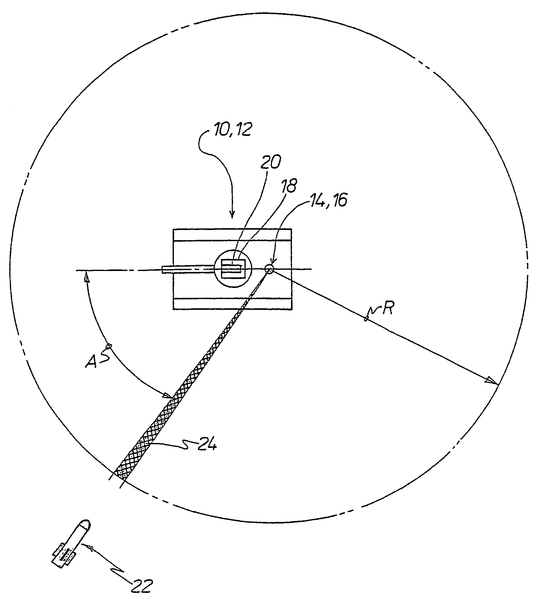
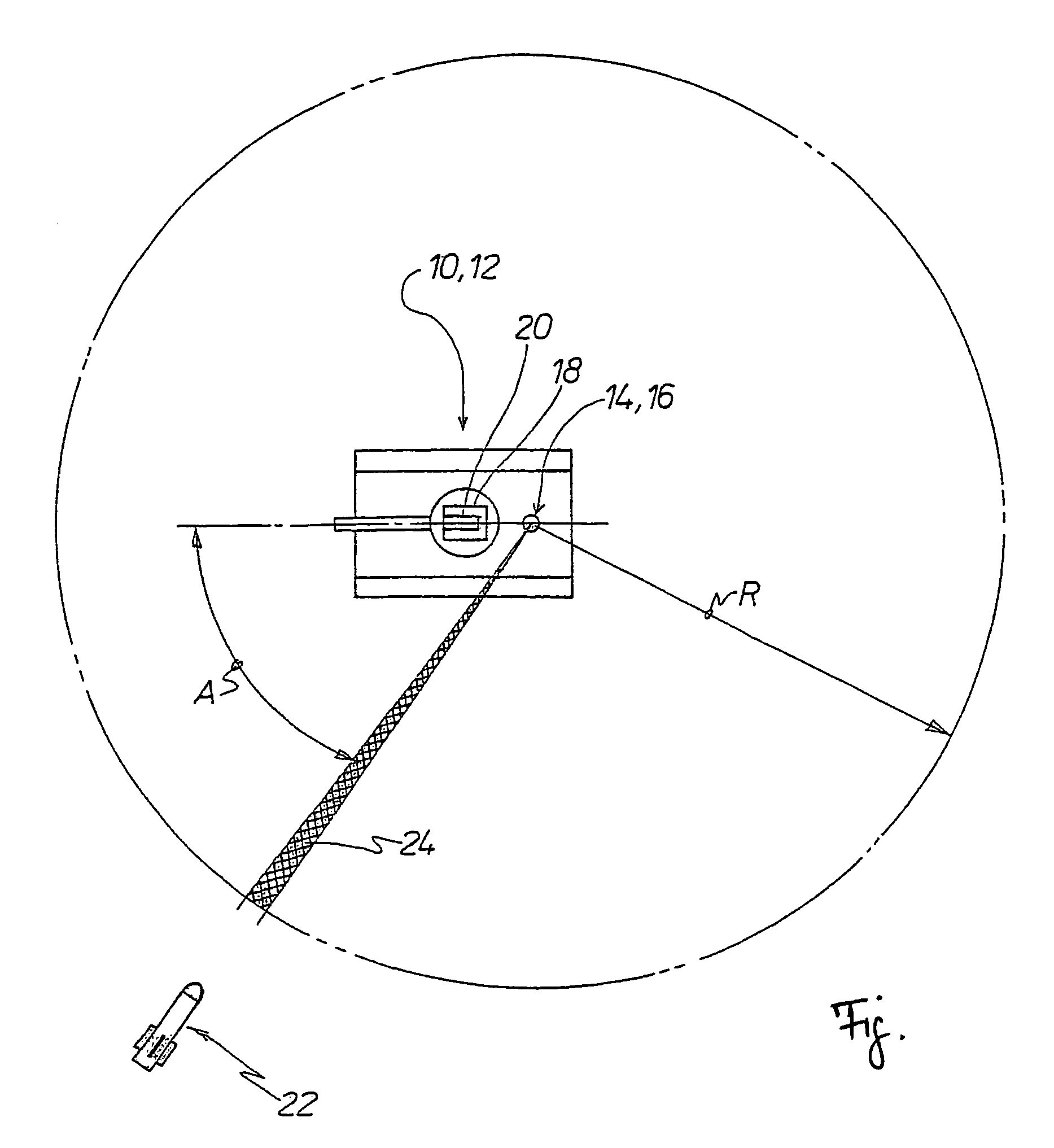
[0020]The Figure is a view from above of an armoured vehicle 10 with an object self-protection apparatus 12 having a monitoring device 14 which is fixed with respect to the object and which is formed by a passive sensor device 16, and a launch container 18, in particular for fragmentation projectiles, which has a target-tracking radar device 20 for detecting the approach movement of a missile 22 to be defended against.

[0021]The passive sensor device 16 can be formed by an image-producing and image-processing IR sensor device or an image-producing and image-processing UV sensor device. The passive sensor device 16 is in the form of a panoramic sensor system with a high level of angular measuring accuracy. That is diagrammatically indicated by the radius R and the narrow radial area region 24 in crossed hatching. The angle A at which the missile 22 to be defended against is approaching the vehicle 10 is determined with a high degree of measuring accuracy by means of the passive sensor...


PUM


Abstract

An object self-protection apparatus (12) having a monitoring device (14) which is fixed with respect to the object and a launch container (18), in particular for fragmentation projectiles, which has a target-tracking radar device (20) for the approach movement of a missile (22) which is to be defended against. The monitoring device (14) which is fixed with respect to the object and the target-tracking radar device (20) are connected together with an aiming drive for the launch container (18). Hereby, an expensive search radar is replaced by a passive sensor device (16) forming the monitoring device (14) which is fixed with respect to the object. The passive sensor device (16) generates accurately measured angular information in respect of the approaching missile (22). The distance and the speed of the missile (22) are then determined by the target-tracking radar device (20).

Description

BACKGROUND OF THE INVENTION[0001]1. Field of the Invention[0002]The invention concerns an object self-protection apparatus, consisting of a monitoring device which is fixed with respect to the object for vectoring a target-tracking radar device, for the close-range determination of the distance and speed of a missile which is to be defended against, located on a launch container which can be aimed at the threat represented by the missile.[0003]2. Discussion of the Prior Art[0004]An object self-protection apparatus of that kind is known from DE 100 24 320 A1. Described therein is a radar device with a planar antenna comprising grouped individual radiating devices for object self-protection against the threat from an attacking missile, wherein the individual radiating devices are arranged in at least one vertically oriented group as monitoring radar on the substructure, which is fixed with respect to the object, of the aiming drive for a launch container for fragmentation projectiles,...

Claims


Application Information

Patent Timeline
IPC IPC(8): G01S13/00G01S13/72F41G5/08F41G7/22F41H11/02
CPCF41G5/08F41G7/224F41H11/02G01S13/867
Inventor PAPPERT, GUNNARGUNTHER, ANDREASKOCH, VOLKER
Owner DIEHL BGT DEFENCE GMBH & CO KG
Learn More