Sensor module and method for producing a sensor module

a technology of sensor modules and sensors, applied in the field of sensors, can solve problems such as the influence of sensor characteristics of sensor elements, and achieve the effects of improving the measurement accuracy of sensor elements, simple and rapid manner, and being easy to realiz

Active Publication Date: 2013-02-21
ROBERT BOSCH GMBH
View PDF2 Cites 7 Cited by
  • Summary
  • Abstract
  • Description
  • Claims
  • Application Information

AI Technical Summary

Benefits of technology

[0005]The example method for producing a sensor module according to the present invention may have the advantage that the sensor element is fixed in place on the line part only after the line part has been extrusion-coated with the plastic material in order to produce the housing. This ensures that the heat and pressures occurring during the injection-molding process do not adversely affect the sensor characteristic of the sensor element. The measuring accuracy of the sensor element is therefore increased. In addition, a single-stage injection process suffices. Another advantage is that the sensor element is fixed in place on the line part in particular only in force-fitting and / or form-fitting manner, so that it is possible to mount the sensor element on the line part in a simple and rapid manner even after the housing has been produced. The housing preferably has a recess in the area of the receiving region, in which the sensor element is fixed in place on the line part. The example method according to the present invention makes it possible to form a recess which is only relatively small, because the easily realizable force- and form-fitting affixation of the sensor element on the line part is readily possible also within a relatively small recess. The sensor element is preferably clamped into the receiving region, so that no complicated soldering, bonding or joining techniques are required. To form the recess, the second production step is carried out in such a way, for instance, that during the injection molding process a slider element is situated in the area of the recess to be formed, which has an outer geometry that corresponds to the recess to be formed, or it is carried out in such a way that a holding element, which has an outer geometry that corresponds to the recess to be formed, holds the line part in the region of the recess to be formed. The line part is electrically conductive and preferably includes a metallic line part, so that the sensor element is able to be contacted from outside the housing via the line part. The sensor element preferably includes an electrical, electronic, mechanical and / or micromechanical sensor, especially preferably an acceleration sensor, an angular acceleration sensor, a sensor for measuring an electrical field, and / or a sensor for measuring a magnetic field (e.g., a Hall-effect sensor).

Problems solved by technology

This method has the disadvantage that the line part is first fitted with the sensor element and the injection molding process is carried out only subsequently, so that the sensor characteristics of the sensor element can be affected by the forces arising during the injection-molding process and also by the produced heat.

Method used


Image

  • Sensor module and method for producing a sensor module
  • Sensor module and method for producing a sensor module
  • Sensor module and method for producing a sensor module

Examples


Embodiment Construction

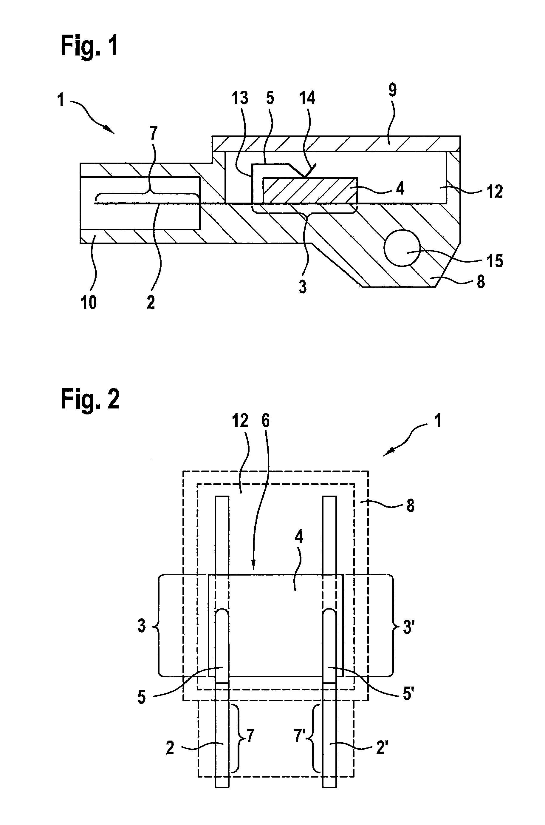
[0020]In the various figures, identical parts have always been provided with the same reference symbols and are therefore usually labeled or mentioned only once.

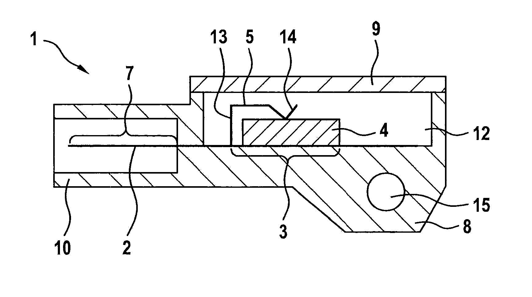
[0021]FIG. 1 shows a schematic sectional view of a sensor module 1 according to a first specific embodiment of the present invention. Sensor module 1 has a line part 2 produced in a first production step, which is developed as metallic line part. Line part 2 has a receiving region 3, in which a sensor element 4 is to be affixed in force- and form-fitting manner. In addition, sensor element 1 has a further line part 2′, which cannot be seen in the illustration in FIG. 1 for reasons of perspective, since further line part 2′ is situated behind line part 2 when viewed from the reader's perspective. Further line part 2′ has a similar design as line part 2. In a second production step, line part 2 and further line part 2′ are partially extrusion-coated with a plastic material in an injection-molding process, so that a housing 8 i...


PUM

PropertyMeasurementUnit
angleaaaaaaaaaa
angleaaaaaaaaaa
axis of rotationaaaaaaaaaa

Abstract

A method for producing a sensor module, in which a line part is provided in a first production step, which includes at least one receiving region for the force-fitting and/or form-fitting accommodation of a sensor element, and in a second production step for producing a housing, the line part is extrusion-coated with a plastic material in such a way that the at least one receiving region remains generally free of plastic material, and the sensor element is fixed in place in force-fitting and/or form-fitting manner in the at least one receiving region in a third production step.

Description

CROSS REFERENCE[0001]The present application claims the benefit under 35 U.S.C. §119 of German Patent Application No. DE 102011081016.1 filed on Aug. 16, 2011, which is expressly incorporated herein by reference in its entirety.FIELD OF THE INVENTION[0002]The present invention relates to a sensor module.BACKGROUND INFORMATION[0003]A conventional sensor module is described in German Patent Application No. DE 10 2007 057 441 A1. To produce the sensor element, a line part is fitted with a sensor element and subsequently extrusion-coated with a plastic material in a two-stage injection molding process in order to produce a housing. On one side, the line part forms the contacts for a mating plug, and on the other side, it forms the contacts to the sensor element. This method has the disadvantage that the line part is first fitted with the sensor element and the injection molding process is carried out only subsequently, so that the sensor characteristics of the sensor element can be affe...

Claims


Application Information

Patent Timeline
Patent Type & Authority Applications(United States)
IPC IPC(8): H05K7/02B23P11/00
CPCG01D11/245H05K5/0078Y10T29/49885B81B2201/0235B81C1/00333
Inventor HORTIG, MICHAELSCHRIMPF, THOMAS
Owner ROBERT BOSCH GMBH
Why Eureka
Try Eureka