Feed device intended for mounting in a fuel tank

a technology for feeding devices and fuel tanks, which is applied in the direction of machines/engines, containers, instruments, etc., can solve the problems of high material consumption, high manufacturing cost of baffles,

Inactive Publication Date: 2003-07-22
CONTINENTAL AUTOMOTIVE GMBH
View PDF3 Cites 14 Cited by
  • Summary
  • Abstract
  • Description
  • Claims
  • Application Information

AI Technical Summary

Problems solved by technology

The baffle is consequently highly cost-intensive to manufacture.
Furthermore, the baffle requires a high and therefore cost-i

Method used


Image

  • Feed device intended for mounting in a fuel tank
  • Feed device intended for mounting in a fuel tank
  • Feed device intended for mounting in a fuel tank

Examples


Embodiment Construction

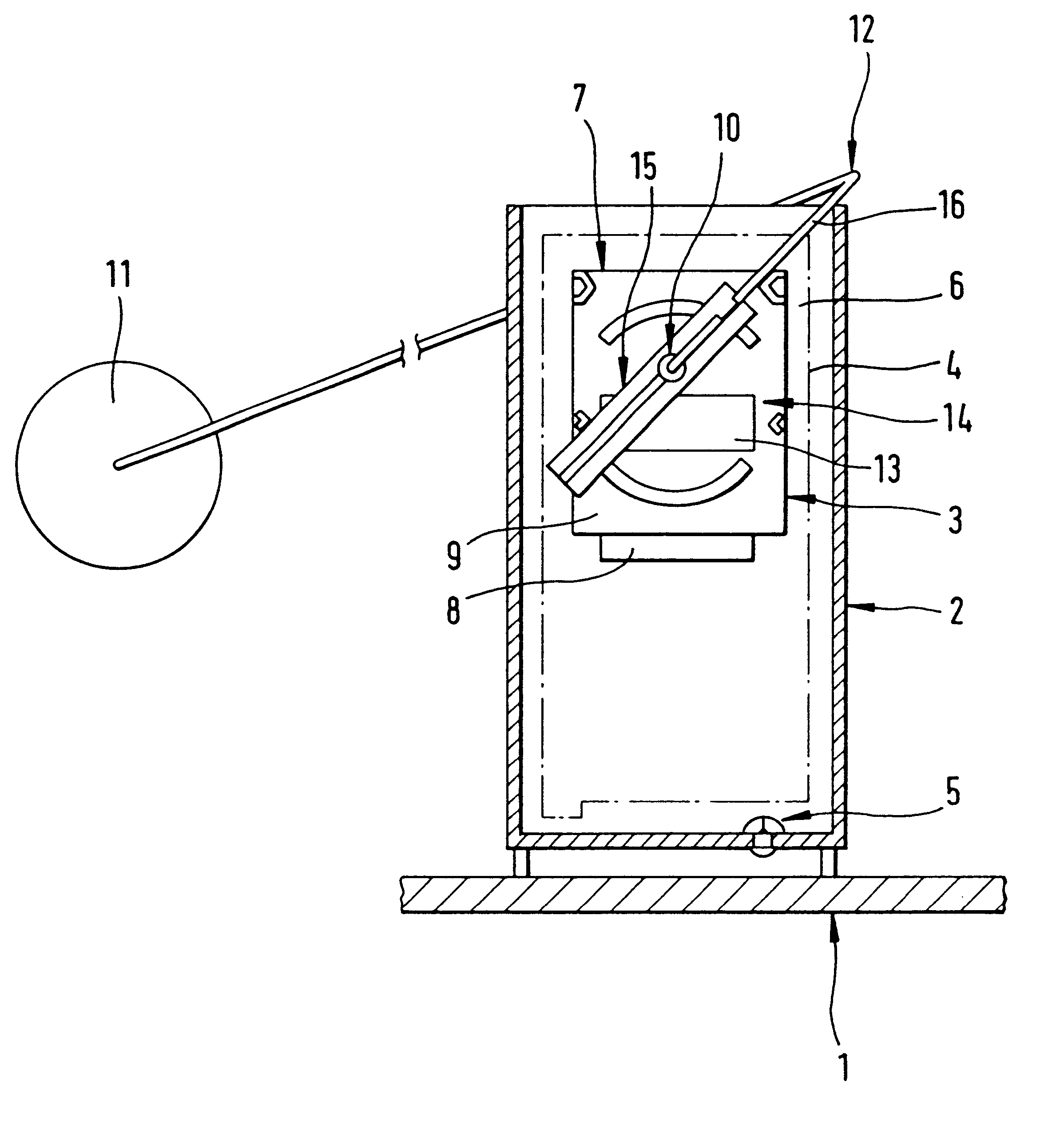
FIG. 1 is a longitudinal sectional view of a baffle 2 arranged in a bottom region of a fuel tank 1. The baffle 2 includes a filling-level sensor 3 and a feed unit 4 indicated by dashes and dots in the drawing. The feed unit 4 feeds fuel out of the baffle 2 to an internal combustion engine which is not illustrated. A bottom valve 5 is arranged in the baffle for filling the baffle 2 with fuel.

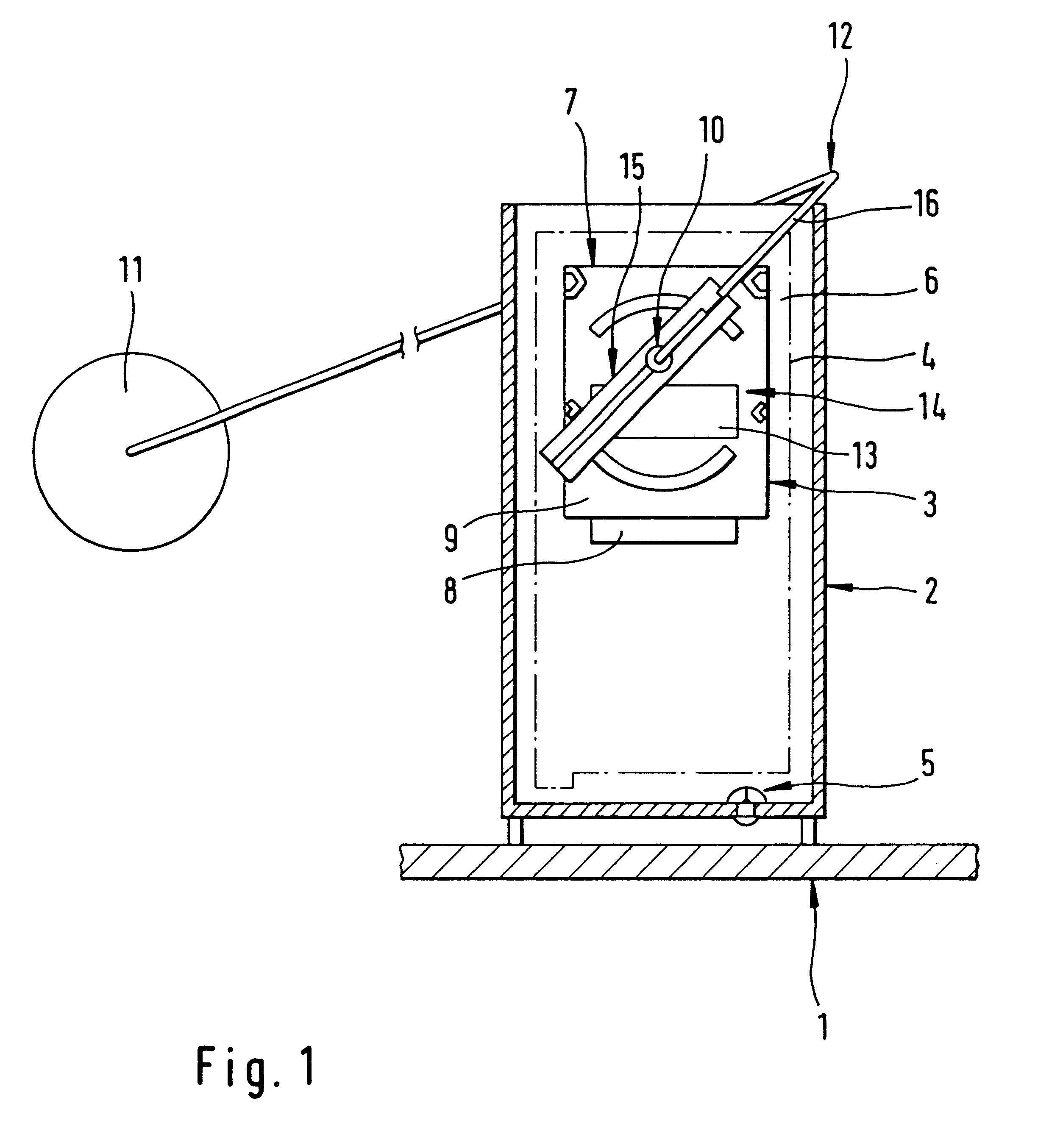
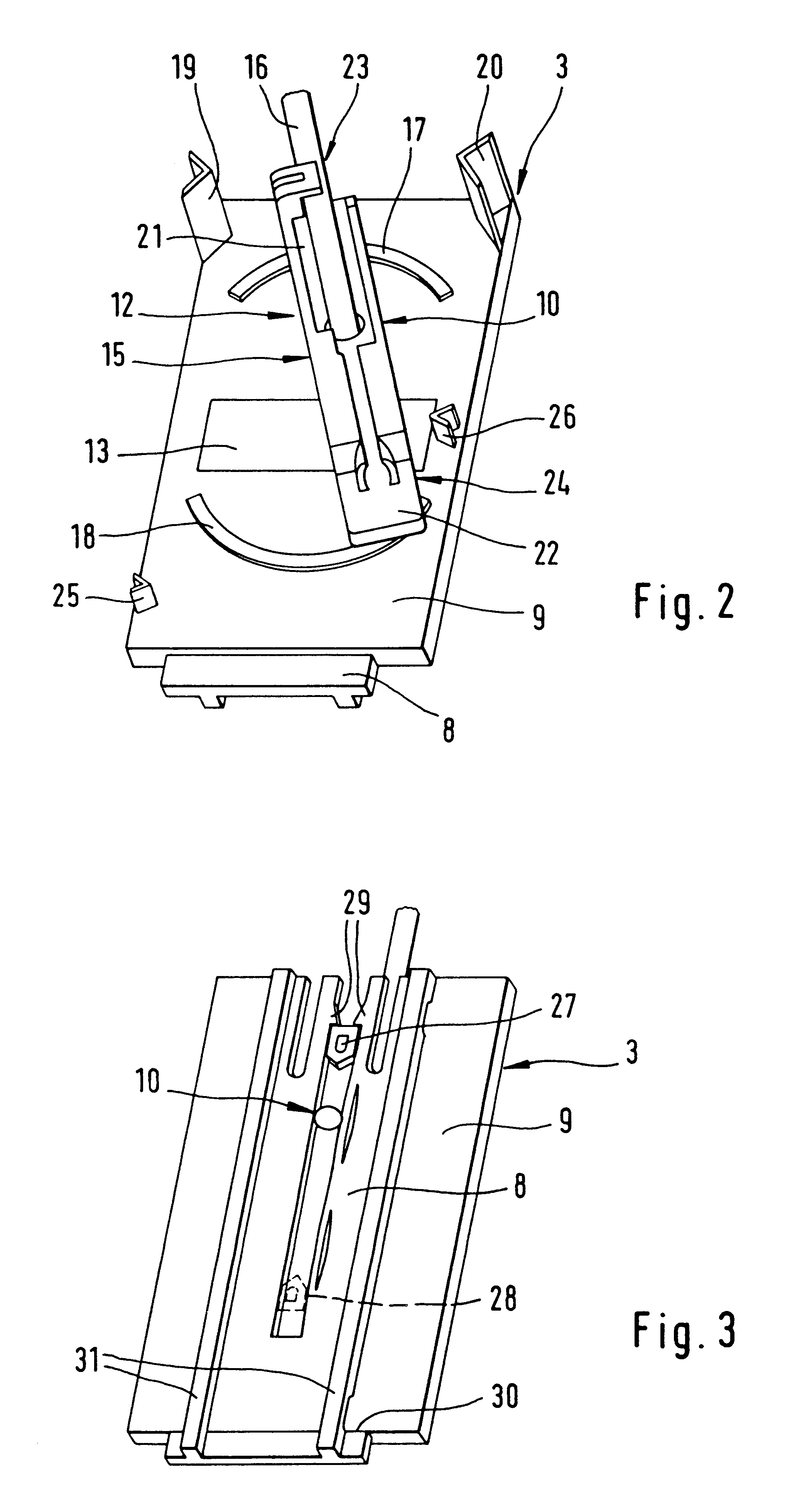
The filling-level sensor 3 is fastened to a vertical wall 6 inside the baffle 2 via a carrier 7. The wall 6 may comprise part of the feed unit 4 or part of the baffle 2. The carrier 7 includes a first carrier part 8 connectable to the wall 6 and a second carrier part 9 positively connected to the first carrier part 8. The second carrier part 9 has a mounting 10 in which a lever arm 12 carrying a float 11 is pivotally received. A resistance slide track 13 of a position sensor 14 designed as a potentiometer is also arranged on the second carrier part 9. As an alternative, the position sensor 14 may...


PUM


Abstract

In a feed device with a filling-level sensor fastened to a wall of a baffle, the filling-level sensor has a lever wire for holding a float. A carrier for mounting the filling-level sensor to a wall of the baffle is connectable to the wall in at least two different orientations. The pivoting range of the float is set by the selected orientation of the carrier on the wall. The feed device is consequently suitable for use in differently constructed fuel tanks.

Description

1. Field of the InventionThe present invention relates to a feed device for installation in a fuel tank having a baffle for collecting fuel, a feed unit for feeding fuel out of the baffle, and a filling-level sensor having a lever arm carrying a float pivotally arranged in a mounting or a carrier arranged on the baffle.2. Description of the Related ArtFeed devices having baffles in which feed units and filling level sensors are arranged are often used in fuel tanks of present-day motor vehicles. The feed units are supported on the bottom of the fuel tank and are designed as a structural unit together with the baffle. The baffle has a guide with a plurality of orifices arranged at different heights. A carrier is arranged in the guide and has a lug for interlocking with one of the orifices. Accordingly, the carrier is connectable to the baffle at different heights thereby allowing standardized components of the feed device to be used in differently constructed fuel tanks which require...

Claims


Application Information

Patent Timeline
IPC IPC(8): B60K15/077F02D33/00F02M37/00
CPCB60K15/077B60K2015/03217B60K2015/03453B60K2015/03467F02D33/003F02M37/0082Y10T137/8342
Inventor KORST, OTTOPANTRING, DETLEF
Owner CONTINENTAL AUTOMOTIVE GMBH
Why Eureka
Try Eureka