Implant For Occluding a Body Passage

Active Publication Date: 2007-12-06
CARAG AG
View PDF13 Cites 61 Cited by
  • Summary
  • Abstract
  • Description
  • Claims
  • Application Information

AI Technical Summary

Benefits of technology

[0011] the implant forming in a first state an elongated article extending along a longitudinal axis, the implant being adapted in the first state for insertion into the circulatory system and the implant being adapted to be brought into a second state in the circulatory system, wherein the distance between the holders being red

Problems solved by technology

However, sometimes, the opening in the passage is such, that the occluding body is not big enough to securely close the passage.
These im

Method used


Image

  • Implant For Occluding a Body Passage
  • Implant For Occluding a Body Passage
  • Implant For Occluding a Body Passage

Examples


Example

[0023] The device according to the invention is based on the implants disclosed in WO 02 / 38051, the disclosure thereof is incorporated in this description by reference.

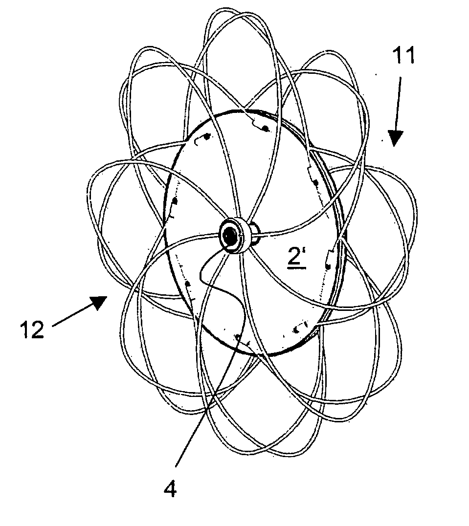
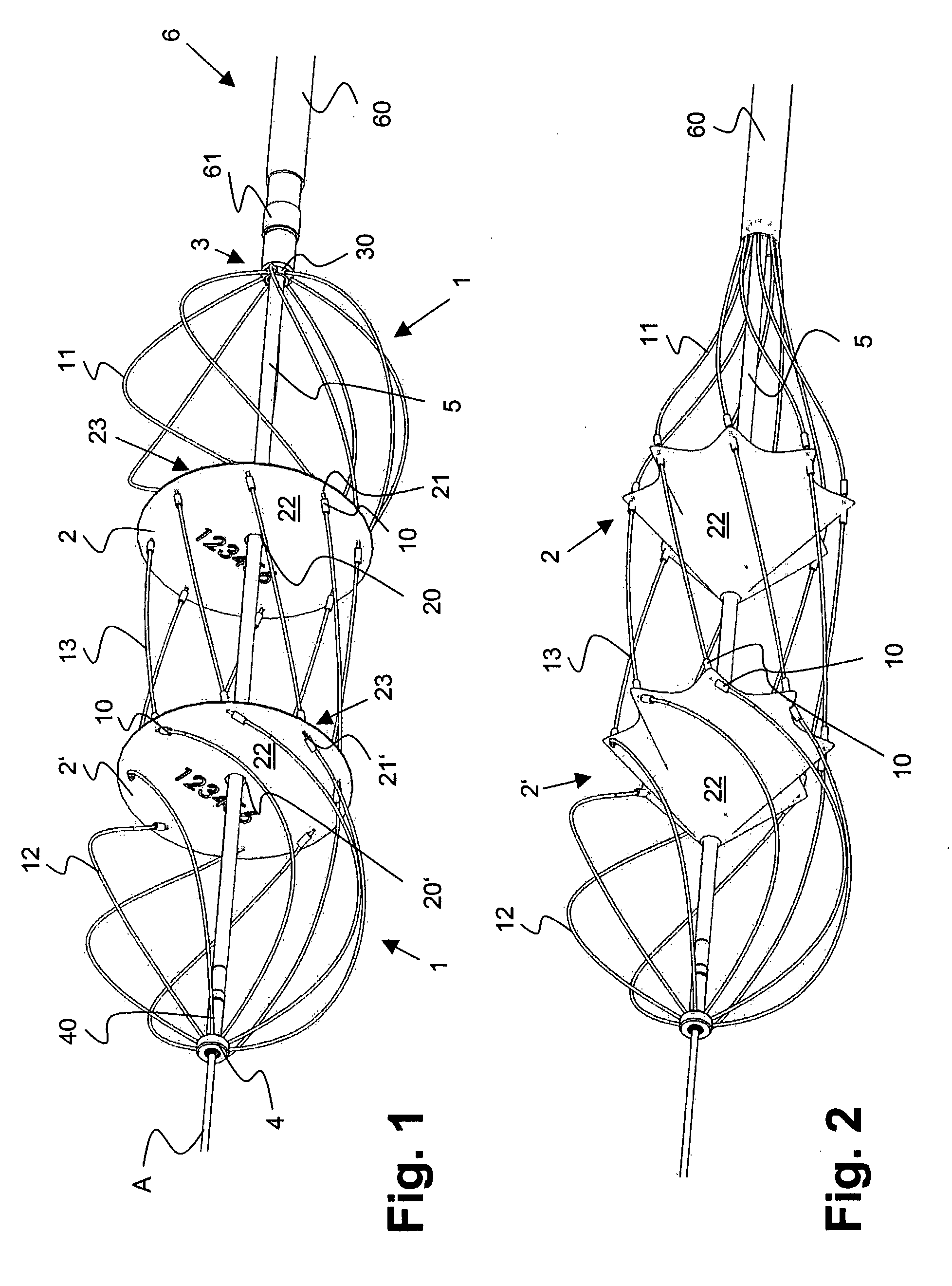
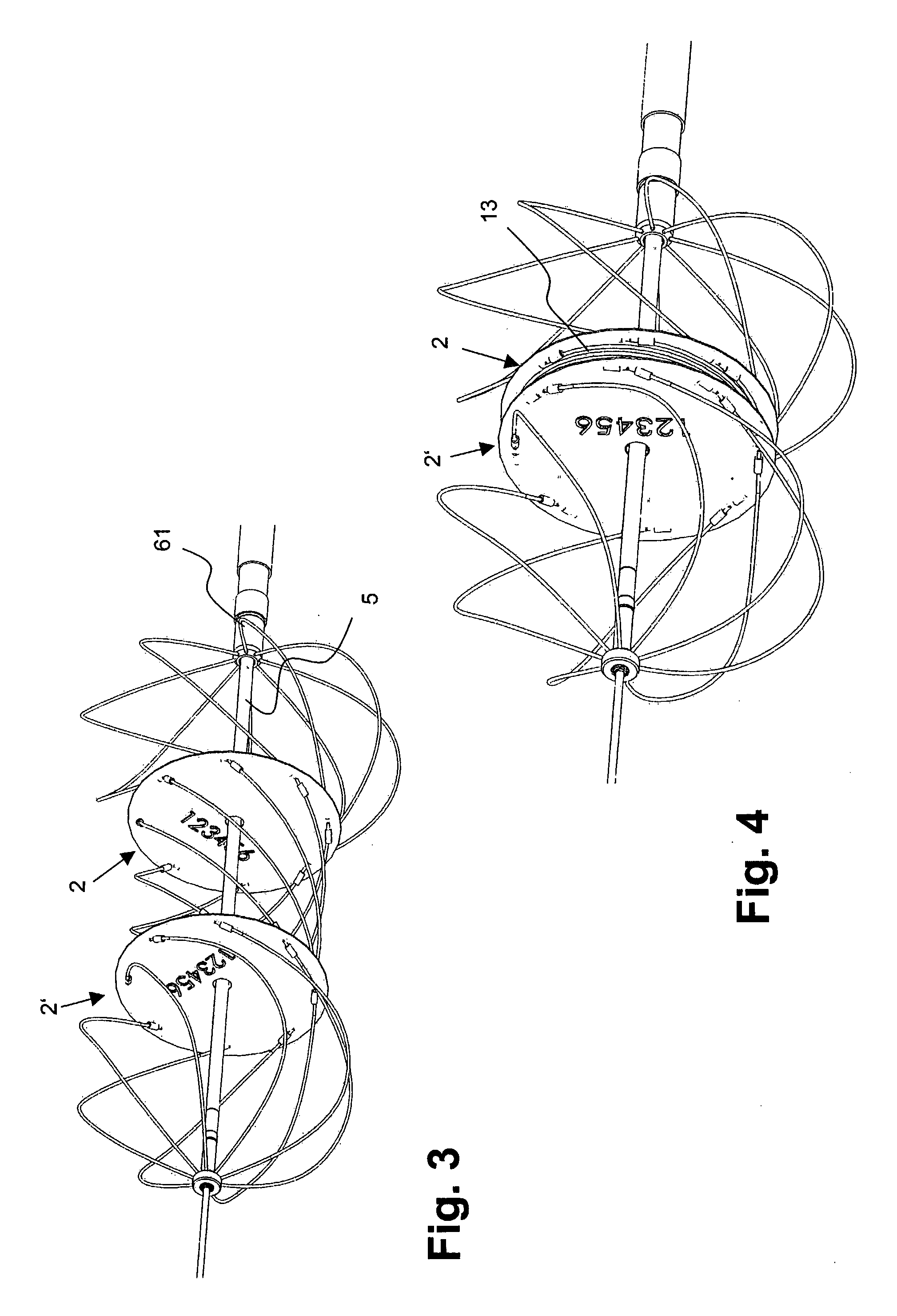
[0024] The inventive device is employed as an implant for closing an internal passage, for example, an aperture in the atrial septum or the ventricle septum of a heart, or in another human or animal body channel which one wishes to close. The implant is compressible for insertion through a delivery mechanism, such as a body vein, and is deployable or expansible for occluding the passage in the circulatory system when arrived at the position of the intended closing spot.

[0025]FIG. 1 shows the implant of the present invention in an initial state, i.e., before the device is applied to the passage in a circulatory system, compressed (luring its insertion and deployed after it has arrived at the intended closing spot.

[0026] The implant comprises a plurality of thin elongate members 1, such as wires or threads, a first o...


PUM


Abstract

An implant for occluding a passage in a circulatory system of a human body comprises elongate members (1) which can be twisted into fixation structures and at least two occluding bodies (2, 2′) being attached to the elongate members (1) and being arranged at a distance to each other. This implant combines the advantages of a single occluding body implant with the advantages of a double occluding body implant.

Description

FIELD OF THE INVENTION [0001] The present invention generally relates to an implant for closing a passage in a circulatory system and more particular for closing a body passage of a human body, for example an aperture through the atrial septum or the ventricle septum of a heart or in a body channel. BACKGROUND OF THE INVENTION [0002] A well-working implant for occluding a passage in a circulatory system is disclosed in WO 02 / 38051. This implant has its particular application as a cardiological implant by means of which it is possible, for example, to close an aperture through the atrial septum or the ventricle septum of a heart. It is arranged to be deployed or built up (i.e., assembled) at a desired location in the body (e.g. the heart), in contrast to known other implants (e.g. so-called umbrellas and sails) that are instead extended as soon as the compressed umbrella leaves its insertion sheath. [0003] This implant includes a plurality of thin wire-like elongate members each havi...

Claims


Application Information

Patent Timeline
IPC IPC(8): A61B17/00A61B17/12
CPCA61B17/0057A61B17/12022A61B2017/00575A61B2017/00623A61B2017/00597A61B2017/00606A61B2017/00619A61B2017/00592
Inventor THOMMEN, DANIELFURRER, SIMONBERNHARD, JEROMECHRISTEN, LUKASEGLI, SILVIAGUNDI, FRANZISKAROBERT, MARCSUTER, FRANZ
Owner CARAG AG
Why Eureka
Try Eureka