Turbomachine

Active Publication Date: 2016-01-21
VITESCO TECH GMBH
View PDF4 Cites 0 Cited by
  • Summary
  • Abstract
  • Description
  • Claims
  • Application Information

AI Technical Summary

Benefits of technology

[0013]If eddying is formed during the transition from the side channel into the pump outlet, it can be minimized by virtue of the fact that the diameter of the opening of the side channel into the pump outlet w

Problems solved by technology

It is disadvantageous that flow losses occur durin

Method used


Image

  • Turbomachine

Examples


Embodiment Construction

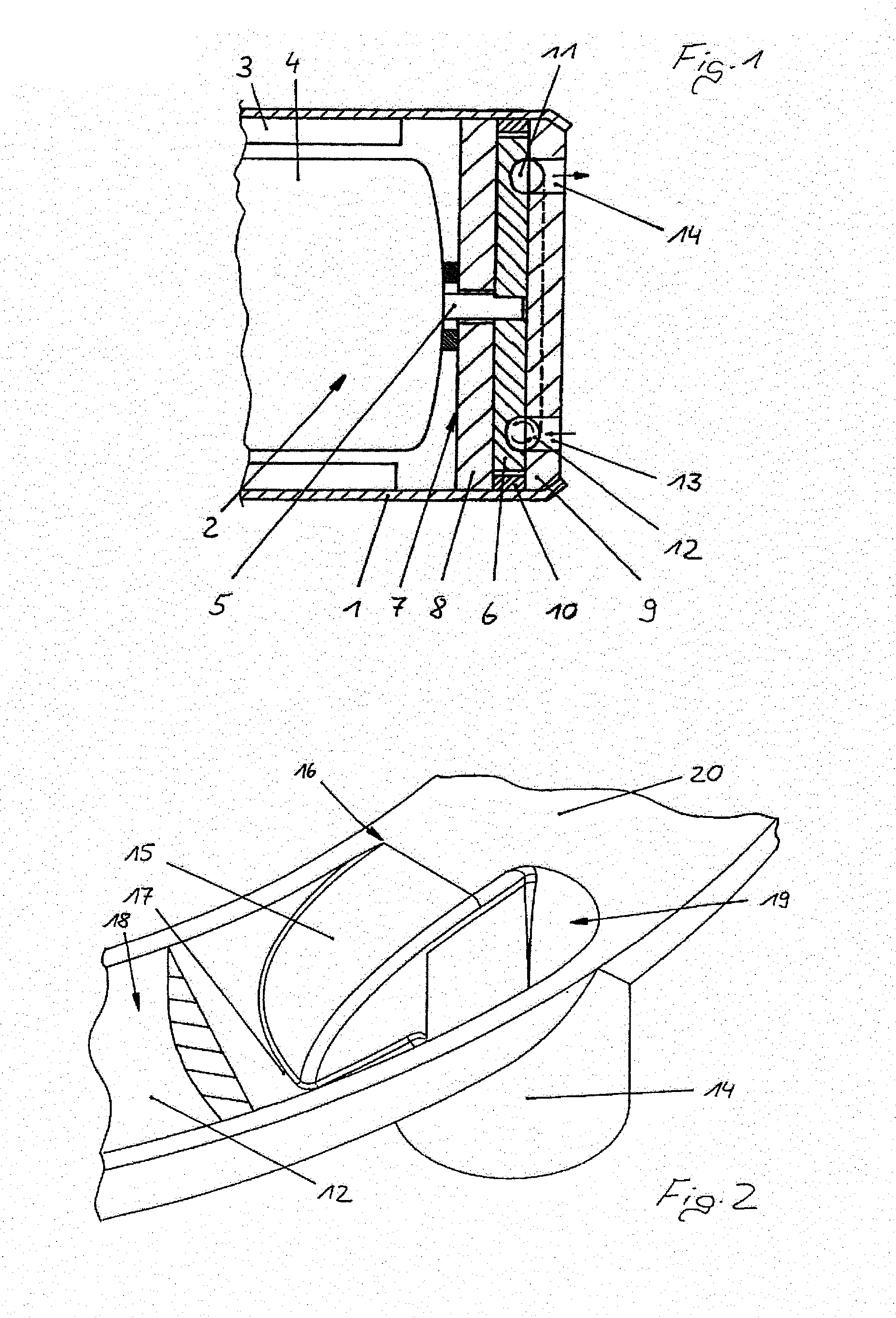
[0017]The turbo machine in FIG. 1 has a housing 1, in which an electric motor 2 is arranged. The electric motor 2 comprises a stator 3 and a rotor 4, which is arranged on a shaft 5. The shaft 5 drives an impeller 6, which is arranged in a pump housing 7. The pump housing 7 consists of a pump bottom 8 and a pump cover 9, which are spaced apart from one another by a spacer ring 10. On the side of the impeller 6 facing the pump cover 9, the impeller 6 comprises a ring of rotor blades 11 which delimit blade chambers. In the pump cover 9 of the pump housing 7, the ring of blade chambers is assigned a side channel 12 so as to lie opposite it. The side channel 12 extends from a pump inlet 13 as far as a pump outlet 14, which are both arranged in the pump cover 9. The pump inlet 13 and the pump outlet 14 usually lie next to one another and are both relocated into the plane of the drawing merely for improved illustration purposes. The blade chambers and the side channel 12 each have a semici...


PUM


Abstract

A turbomachine includes a housing and an electric motor in the housing. The electric motor has a shaft, a stator, and a rotor on the shaft. At least one impeller is arranged in a pump housing and driven by the shaft, the impeller having at least one ring of rotor blades delimiting a ring of blade chambers. A side channel is arranged in the pump housing opposite the ring of blade chambers and extends from the pump inlet as far as the pump outlet. A ramp is arranged at an end of the side channel in a radially inner half of the side channel. The ramp starts from a channel bottom, rises in a flow direction as far as the height of the pump housing wall, and merges with its radially outer half into the pump outlet.

Description

CROSS-REFERENCE TO RELATED APPLICATIONS[0001]This is a U.S. national stage of application No. PCT / EP2013 / 074990, filed on 28 Nov. 2013, which claims priority to the German Application No. DE 10 2012 222 336.3 filed December 2012, the content of both incorporated herein by reference.BACKGROUND OF THE INVENTION[0002]1. Field of the Invention[0003]The subject matter of the invention is a turbomachine having a housing, an electric motor which is arranged in the housing, the electric motor comprising a stator and a rotor which is arranged on a shaft, at least one impeller which is driven by the shaft, has at least one ring of rotor blades which delimit blade chambers, and is arranged in a pump housing, and having a side channel which is arranged in the pump housing, lies opposite in each case one ring of blade chambers, and extends from a pump inlet as far as a pump outlet.[0004]2. Related Art[0005]Turbomachines of this general type are known and are used to deliver liquids, in particula...

Claims


Application Information

Patent Timeline
IPC IPC(8): F04D29/42F04D1/00F04D13/06F04D17/08F04D25/06F04D29/043F04D29/053F04D29/22F04D29/28
CPCF04D29/4206F04D1/00F04D17/08F04D13/06F04D29/426F04D29/043F04D29/053F04D29/22F04D29/28F04D25/06F04D23/008F05B2250/503F04D5/007
Inventor BENDER, KLAUS-WERNERKOPPLER, PETER
Owner VITESCO TECH GMBH
Why Eureka
Try Eureka