
Printed identification band and method of manufacturing same

a technology of identification bands and wrist bands, applied in the field of improved identification bands, can solve the problems of difficult printing of wrist bands, general not particularly aesthetically pleasing, and the inability of spun-bonded polyolefin to withstand high temperatures, and achieve the effect of being relatively economical and efficient to produ

Inactive Publication Date: 2007-12-13
PRINTMARK INDS
View PDF19 Cites 19 Cited by
  • Summary
  • Abstract
  • Description
  • Claims
  • Application Information

AI Technical Summary

Benefits of technology

[0012]Still another object of the present invention is to provide an identification band having the above characteristics and which is relatively economical and efficient to produce.
[0013]Yet a further object of the present invention is to provide an identification band having the above characteristics and which is aesthetically pleasing.
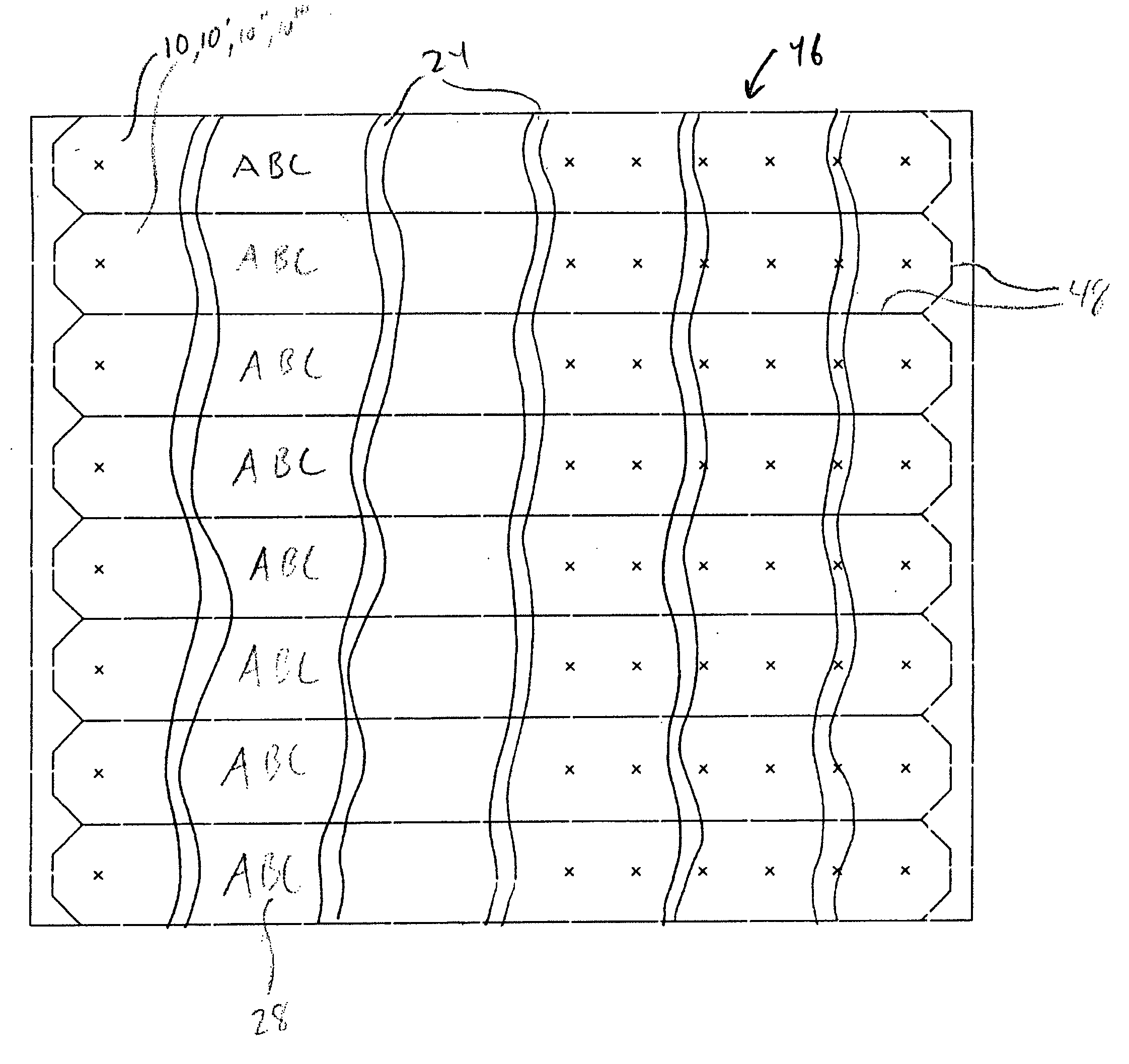
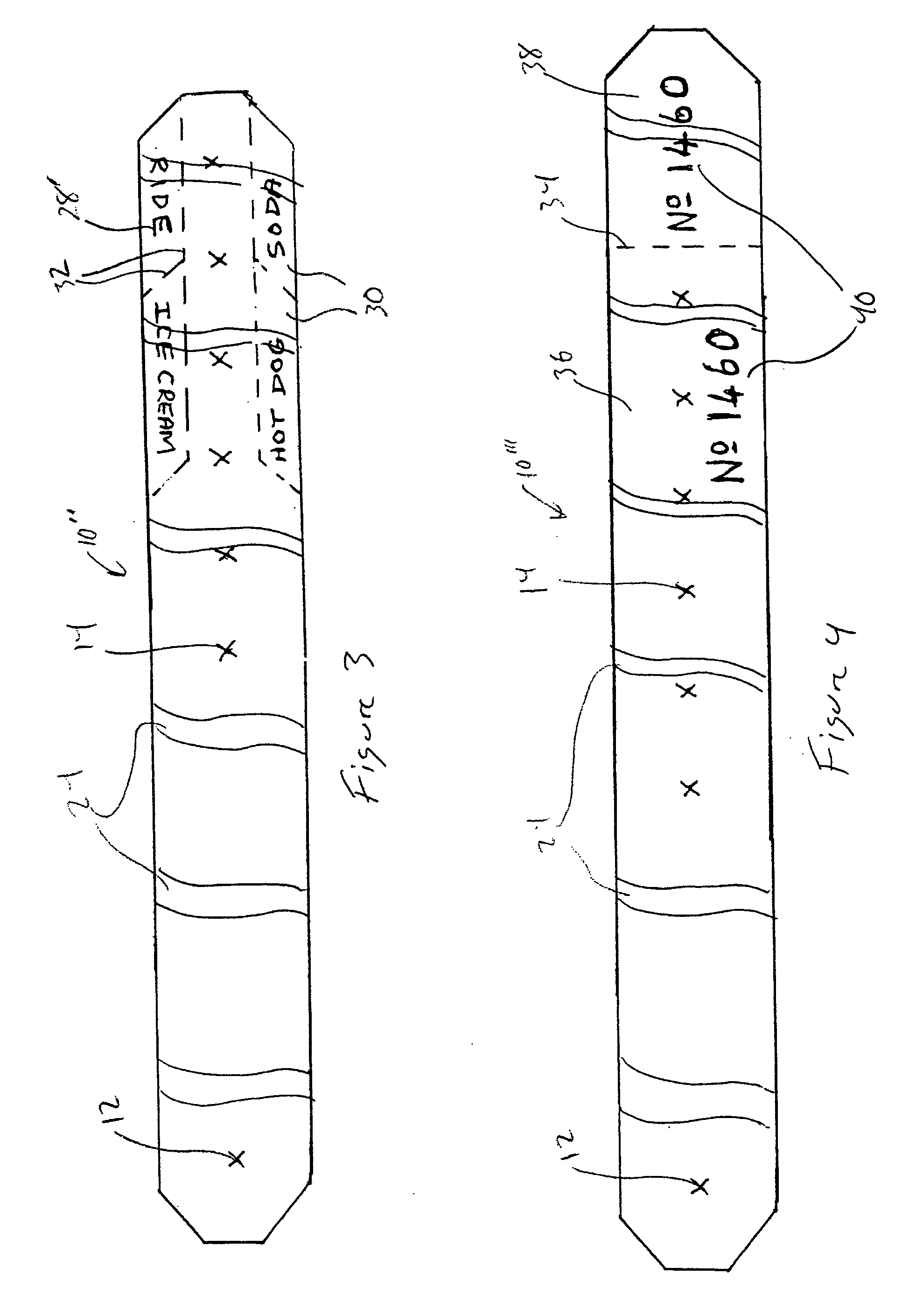
[0015]In some embodiments, the elongated member has a generally rectangular outer periphery. In certain of these embodiments, corners of the generally rectangular outer periphery of the elongated member are rounded or removed in order to enhance wearer comfort. In certain embodiments, the band further includes perforations formed within the generally rectangular outer periphery of the elongated member, which perforations define at least one removable portion of the band. In certain of these embodiments, the at least one removable portion comprises a plurality of tabs which have printed thereon an indication of something for which the tabs are redeemable. In certain embodiments, the at least one removable portion comprises a removable end of the band, and the removable end of the band and a main portion of the band are both printed with corresponding identifiers. In certain embodiments, the identifiers comprise alphanumeric strings of characters.
[0017]Another embodiment allows for a layer of PVC material which is ink-receptive to digital ink to be digitally printed. This PVC sheet may be white or clear. The clear sheets may be printed reading backwards, so that they can be turned over and sealed to a second sheet (usually opaque), which becomes a backer to the top sheet. This way, the digital ink is trapped between the two layers, eliminating any incidents of the ink being able to be scratched off the surface. If a white PVC sheet is used, this is printed forwards-reading on its top surface, and this may also be sealed to a backing layer for additional strength and support.
[0020]In some embodiments, corners of the generally rectangular outer periphery of the elongated member are rounded or removed in order to enhance wearer comfort. In some embodiments, the at least one removable portion comprises a plurality of tabs which have printed thereon an indication of something for which the tabs are redeemable. In some embodiments, the at least one removable portion comprises a removable end of the band, and the removable end of the band and a main portion of the band are both printed with corresponding identifiers. In certain of these embodiments, the identifiers comprise alphanumeric strings of characters.

Problems solved by technology

A common example would be where wrist bands are used to identify ticket holders at a concert or other event—it would be undesirable for a ticket holder, after entering a venue and receiving a wrist band identifying that person as a ticket holder, to be able remove his / her wrist band and give it to another person (e.g., by passing it through a fence) such that this other person would also be able to enter the venue, posing as a legitimate ticket holder.
While the above-described wrist bands may be adequate in performing their identification functions, they are generally not particularly aesthetically pleasing.
In general, the materials from which the wrist bands are formed are difficult to print on, and therefore, any printing thereon is typically done in a single color (typically black).
In addition, spun-bonded polyolefin can not withstand high temperatures, so that wrist bands made from this material can not be passed through high-heat printers, such as digital color printers and copiers.

Method used


Image

  • Printed identification band and method of manufacturing same
  • Printed identification band and method of manufacturing same
  • Printed identification band and method of manufacturing same

Examples


Embodiment Construction

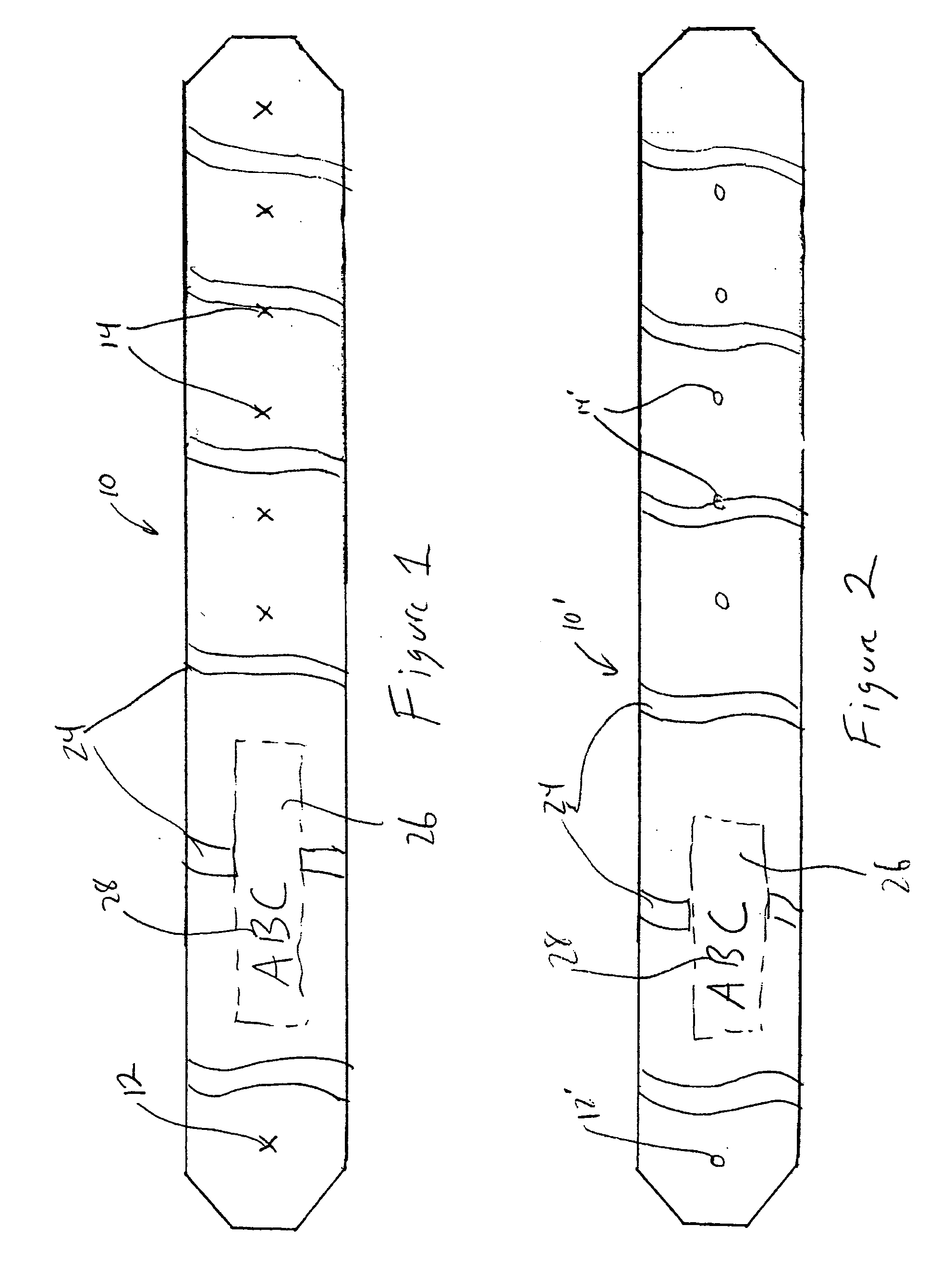
[0041]Referring first to FIGS. 1 and 2, a wrist band 10, 10′ in accordance with the present invention is shown. While the term “wrist band” is used in the specification, it should be understood that it is not necessary that wrist band 10, 10′ be worn on the wrist. Wrist band 10, 10′ may be worn on the ankle, forearm, upper arm, leg, around the neck, or around any other part of the body. Of course, it may be necessary to increase or decrease the size of wrist band 10, 10′ if it is intended to be worn on a part of the body other than the wrist. Identification bands in accordance with the present invention may also be used to identify objects, such as luggage, cycles, watercraft and other vehicles participating in races or the like, and / or for security purposes, such as sealing door handles closed, and for other uses.

[0042]Wrist band 10, 10′ is generally elongate in shape, and formed without pointed edges. The corners thereof may be rounded, or as shown in the Figures, the corners may ...


PUM


Abstract

An identification band includes an elongated member having a front face and a rear face, and having a first opening therein adjacent a first end and a series of openings therein adjacent a second end, the elongated member being formed from a material adapted to accept digital printing ink. A stud is disposed in the first opening, the stud adapted to be passed through one of the series of openings after the band is wrapped around an object. A digital image is printed on at least one of the front face and the rear face of the elongated member, the digital image being composed of digital printing ink.

Description

FIELD OF THE INVENTION[0001]The present invention relates to an improved identification band, for example, a wrist band of the type used to identify persons as being particular individuals or as being a member of an identifiable group, as well as to a method of manufacturing such an improved identification band.BACKGROUND OF THE INVENTION[0002]The use of bands (such as bands which are adapted to be worn on the wrist of a person, as well as those adapted to be worn around other body parts) for identification purposes is well known. Such wrist bands have been used for decades to identify a person as being a particular individual, or to identify the person as being a member of an identifiable group. For example, it is typical when a patient is admitted to a hospital that the patient is given a wrist band having personal information concerning the patient printed thereon. Such identification wrist bands are disclosed, for example, in U.S. Pat. Nos. 2,846,796, 3,020,657, 3,020,658 and 3,...

Claims


Application Information

Patent Timeline
Patent Type & Authority Applications(United States)
IPC IPC(8): A44C5/00
CPCG09F3/005
Inventor SLOOT, ALEXANDER
Owner PRINTMARK INDS
Learn More