Tube pump for removing dross during galvanizing

a tube pump and dross technology, which is applied in the direction of liquid fuel engines, machines/engines, mechanical equipment, etc., can solve the problems of reducing the strength of the dross, so as to reduce the defect, reduce the cost, and reduce the effect of corrosion

Inactive Publication Date: 2021-04-01
THUT BRUNO H
View PDF0 Cites 0 Cited by
  • Summary
  • Abstract
  • Description
  • Claims
  • Application Information

AI Technical Summary

Benefits of technology

[0021]a mechanism for placing the part inside the galvanizing bath in a region of the inlet opening of the inlet conduit, and for removing the part from the galvanizing bath, effective to produce a metal galvanized part with reduced defects, lesser corrosion and / or higher strength.
[0022]The tube pump has various advantages. One advantage is that it presents an economical and efficient way to produce cleaner galvanized parts. No costly dross removing robot or inert gas enclosure are required. Another advantage is that fewer parts are used in that a submergeable base containing a volute chamber is not needed, nor are posts for securing the base to the motor mount. A tube pump is susceptible to the influences of torque since it contains a rapidly rotating impeller that can pump in different directions. Since in the device of this disclosure flow is directed downwards into the inlet conduit, lateral torque on the tube is reduced such that the single tube can contain the forces of the pump, reducing complexity and component material to successfully create this pump. The locations of the inlet and outlet conduits can also be adjusted so as to minimize the torque on the tube pump.
[0023]The unique impeller design as a screw or auger shape allows pumping predominantly vertically instead of to the side, unlike a traditional impeller that pumps to the side. This gives two benefits. The downwards pumping direction allows a “zero-head” scenario, where the inlet and outlet of the pump are essentially level, or the outlet is slightly below the inlet. This means there is no pressure barrier to overcome in order to pump, increasing overall flow rate.

Problems solved by technology

Even if pure zinc bonds directly with the steel, the addition of the dross creates a brittle section of the coating, causing the material to chip if flexed.
The conventional approaches for avoiding or removing dross are both complicated and expensive.
Another approach, raking the dross away by hand, is extremely dangerous due to risk of severe injuries and is a labor intensive approach to dross removal.

Method used


Image

  • Tube pump for removing dross during galvanizing
  • Tube pump for removing dross during galvanizing
  • Tube pump for removing dross during galvanizing

Examples


Embodiment Construction

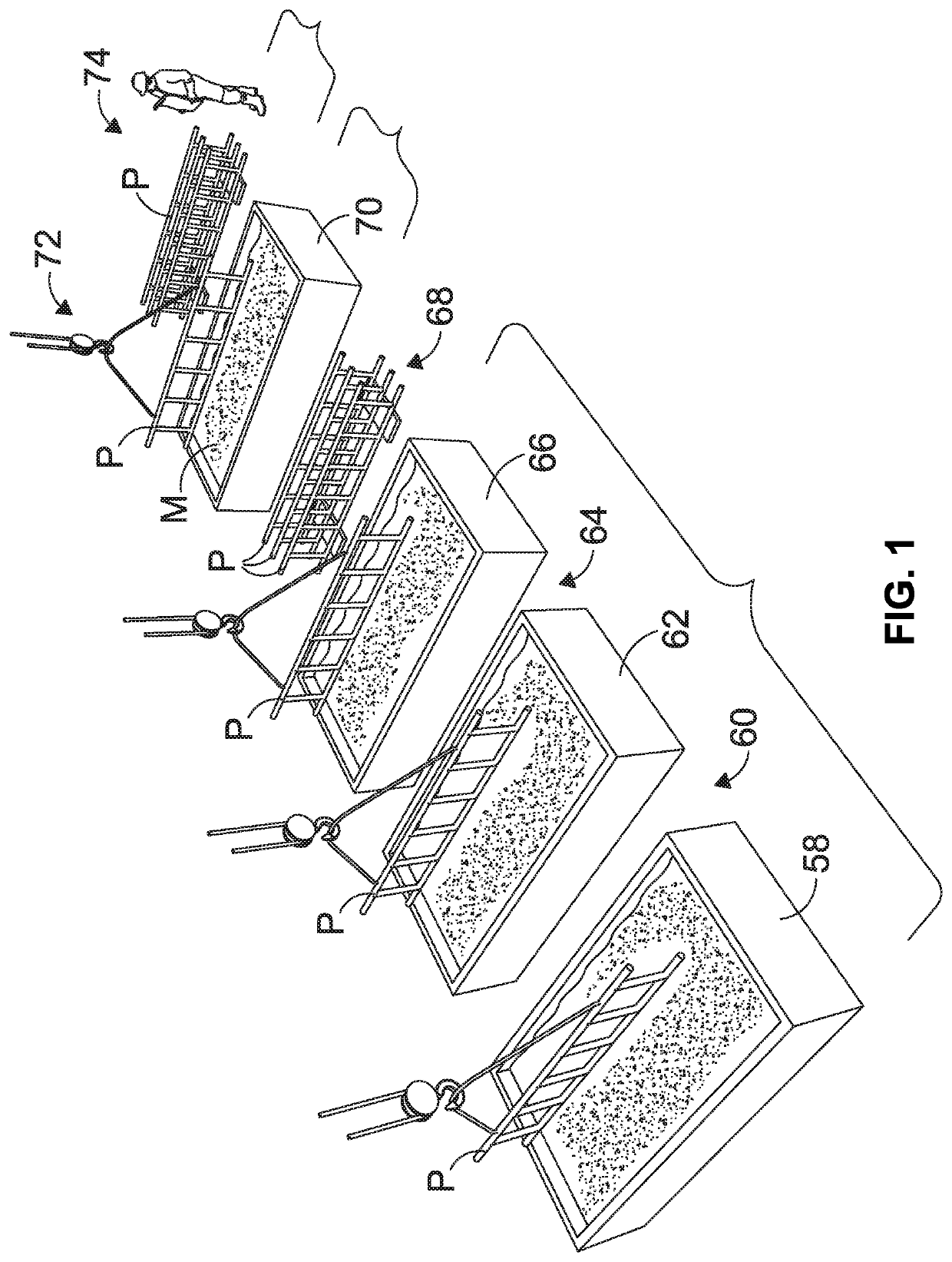
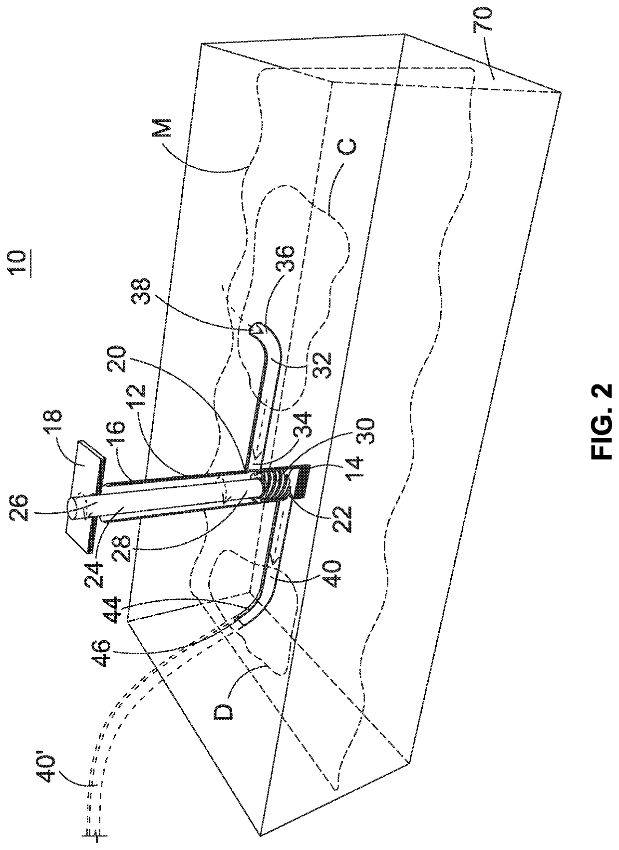
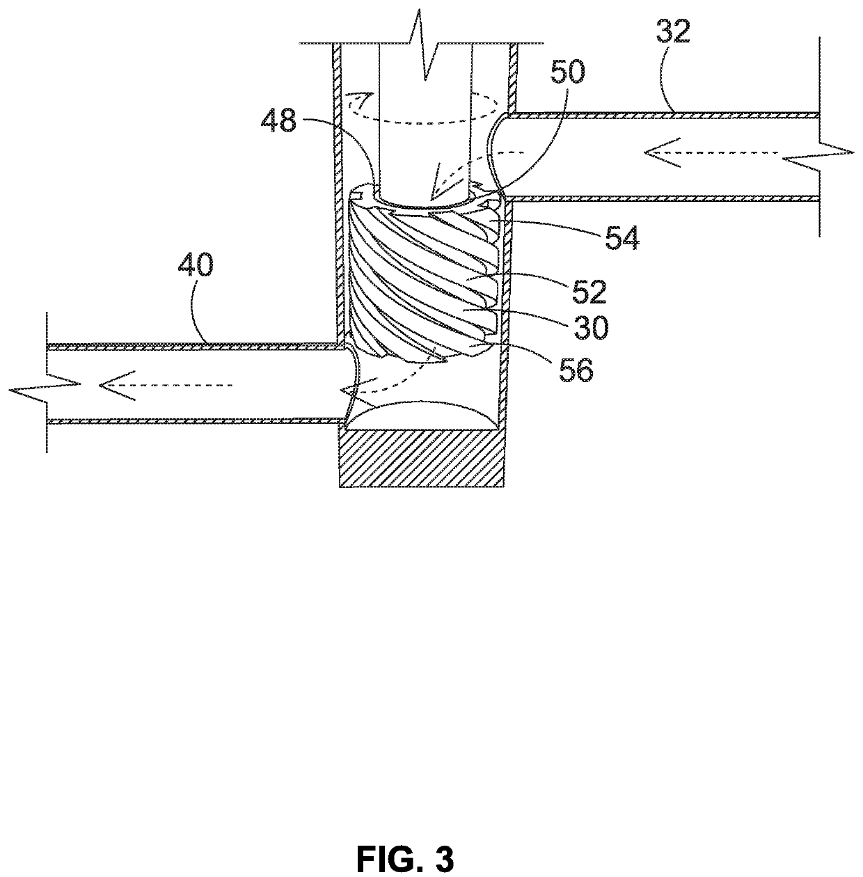
[0027]A tube pump 10 is suitable for use in removing dross during galvanizing and includes a tube 1212 comprised of refractory having a closed off lower end portion 14 and an open upper end portion 16. The lower end portion 14 of the tube 12 is adapted to be submerged in a bath of molten metal M. The galvanizing bath and the other baths are contained by enclosures, for example, the galvanizing bath is surrounded by refractory brick as known in the art. Support structure 18 is disposed outside of the molten metal bath for securing the upper end portion of the tube 12. The tube includes an inlet opening and an outlet opening (shown by 20, 22 in either upper or lower position). The position of the inlet and outlet openings can be reversed. A motor (not shown) is mounted to the support structure and includes a drive shaft (not shown). A pump shaft 24 is comprised of refractory material having upper and lower end portions 26, 28, respectively. The upper end portion 26 of the pump shaft 2...


PUM

PropertyMeasurementUnit
shapeaaaaaaaaaa
strengthaaaaaaaaaa
corrosionaaaaaaaaaa

Abstract

A tube pump includes a tube having a closed off lower end portion and an open upper end portion. The upper end portion of the tube is adapted to be fastened to support structure. The lower end portion is adapted to be submerged in molten metal. The tube includes an inlet opening and an outlet opening. A pump shaft is adapted to be connected to a motor driven drive shaft and has upper and lower end portions. The pump shaft extends inside the tube. An impeller is fastened to the lower end portion of the pump shaft and disposed near a lower end portion of the tube. Inlet and outlet conduits are connected to the tube inlet and outlet openings adjacent to a top or bottom of the impeller so that a conduit inlet opening is disposed near the surface of the bath and a conduit outlet opening is disposed remote from the conduit inlet opening. The tube pump removes dross from the galvanizing bath to produce galvanized parts having improved properties.

Description

TECHNICAL FIELD[0001]During galvanizing, metal parts are coated with a molten metal to protect the parts against corrosion. However, the presence of dross in the molten metal galvanizing bath can lead to defects and inferior properties of the galvanized part. In an attempt to work around dross problems, the dross can be mechanically removed from the molten metal bath or limited in formation but these are costly approaches.BACKGROUND OF THE DISCLOSURE[0002]A typical galvanizing process has multiple steps including submerging a part (e.g., a part made of steel), into a degreasing tank then rinsing. Next the part is submerged in a picking bath containing an acidic solution and then rinsed. Next the part is submerged in a fluxing bath and then dried. One example of a flux is zinc ammonium chloride. The flux aids in the process of the liquid zinc wetting and adhering to the steel of the part. The next step is galvanizing by submerging the part in a galvanizing bath of molten metal. The g...

Claims


Application Information

Patent Timeline
Patent Type & Authority Applications(United States)
IPC IPC(8): C23C2/00C23C2/02F04D7/00F04D29/043F04D3/02
CPCC23C2/003C23C2/02F04D3/02F04D29/043F04D7/00F04D3/00C23C2/06C23C2/30C23C2/0038C23C2/024C23C2/325C23C2/022C23C2/00342
Inventor THUT, BRUNO H.THUT, NIKLAUS
Owner THUT BRUNO H
Why Eureka
Try Eureka