
Decreased lens delamination during ophthalmic lens manufacture

a technology for ophthalmic lenses and molds, applied in the field of molds for forming ophthalmic lenses, can solve the problems of unsuitable patients and relatively slowness, and achieve the effect of reducing the incidence of lens delamination

Inactive Publication Date: 2007-12-13
JOHNSON & JOHNSON VISION CARE INC
View PDF18 Cites 45 Cited by
  • Summary
  • Abstract
  • Description
  • Claims
  • Application Information

AI Technical Summary

Benefits of technology

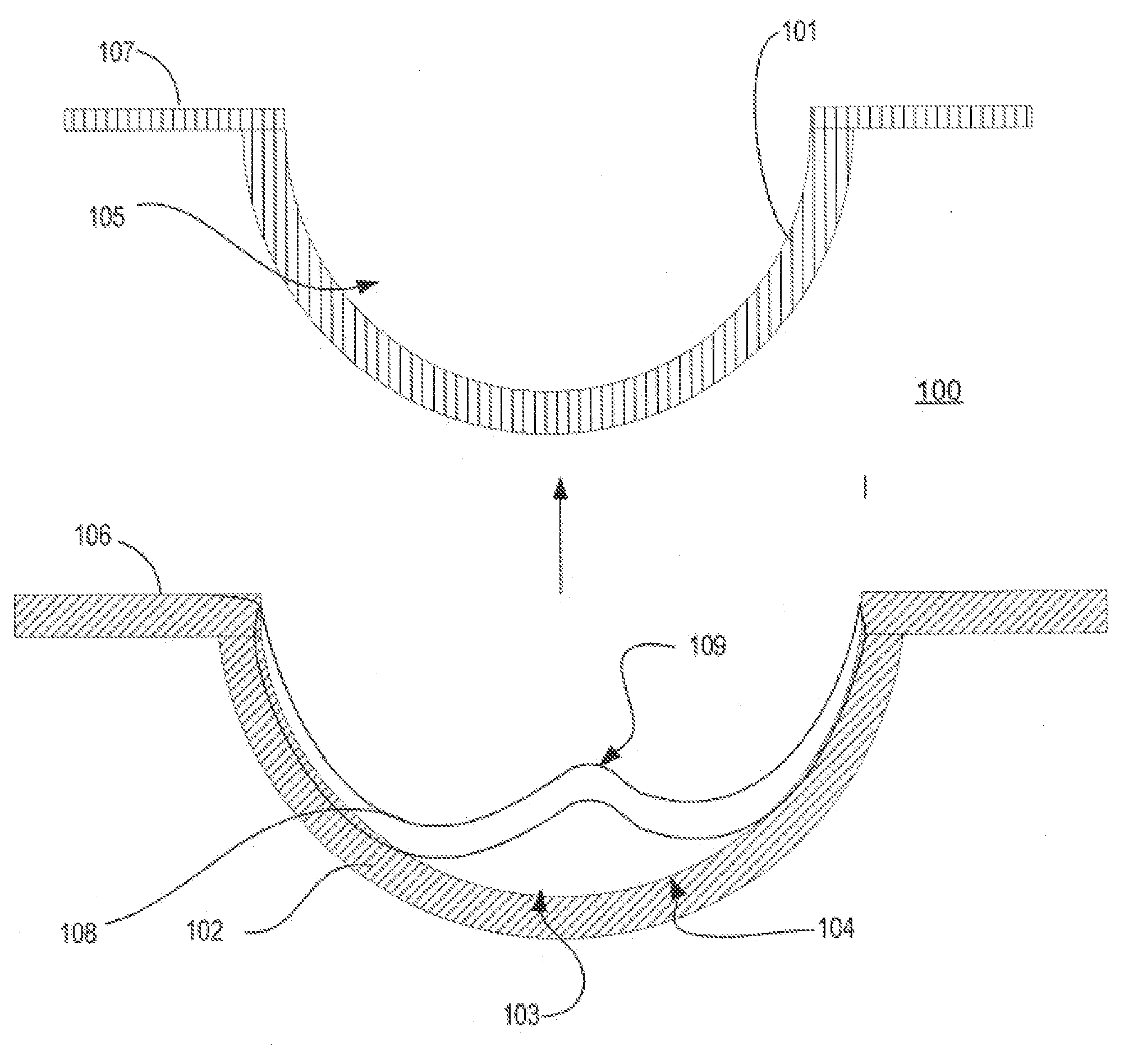
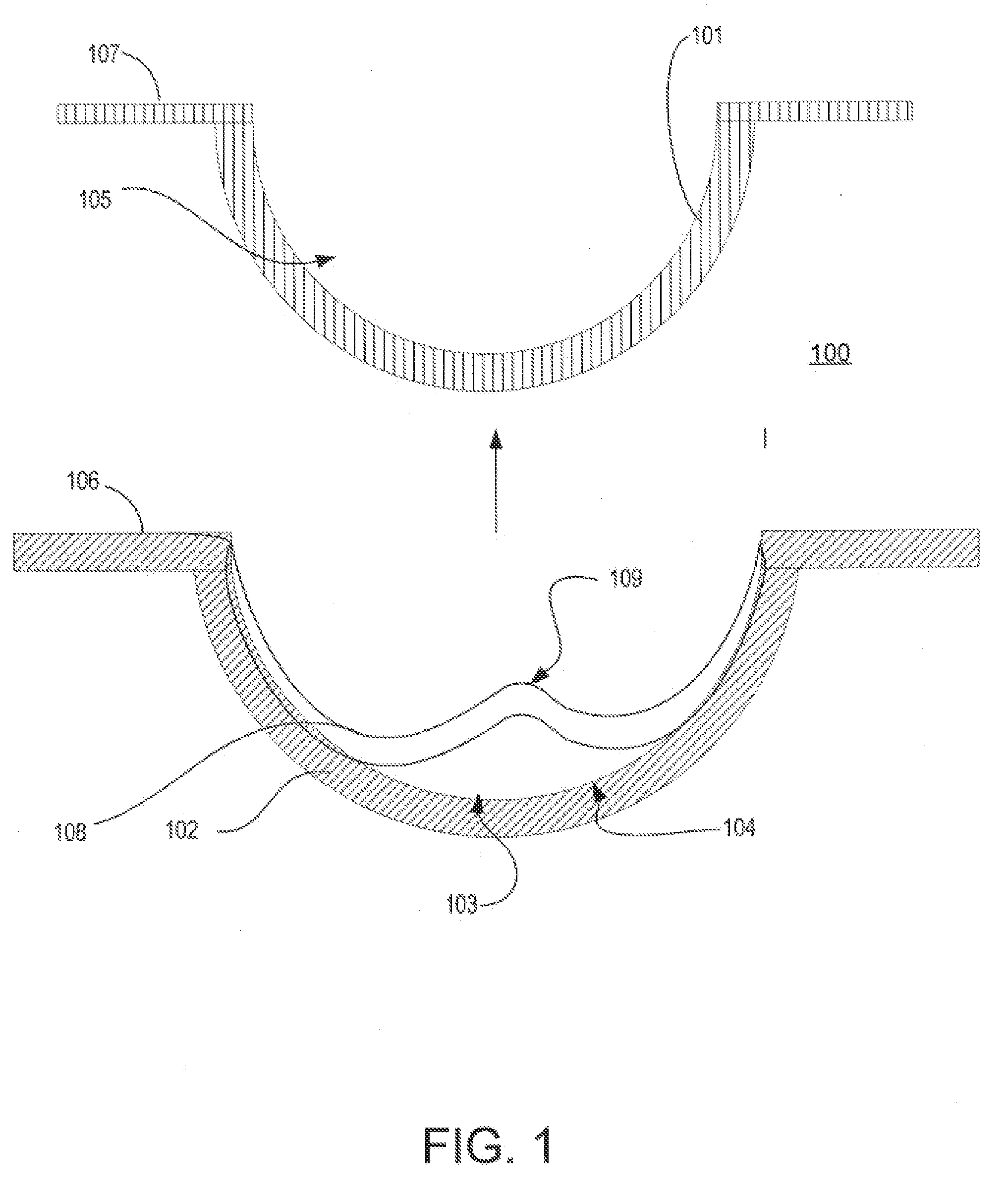
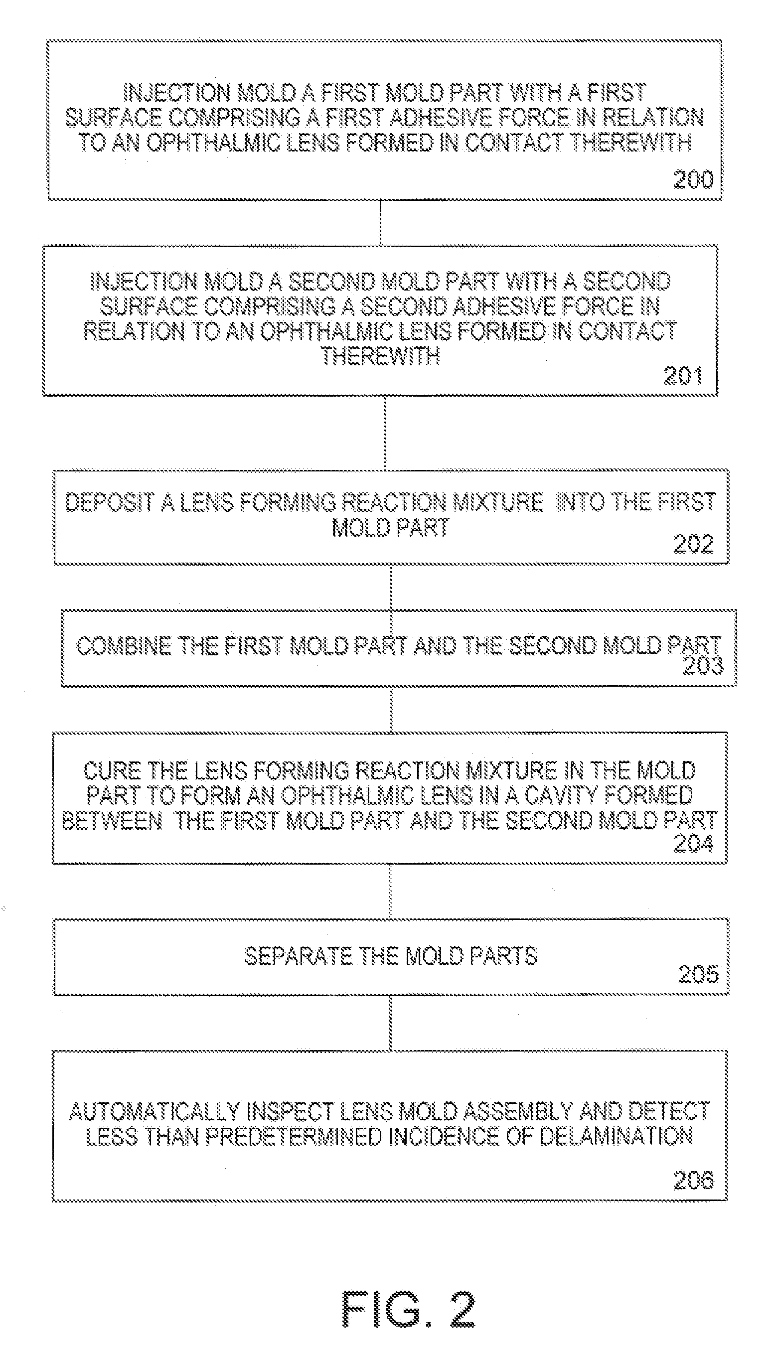
[0010]Accordingly, the present invention provides methods and apparatus for decreasing the incidence of lens delamination during lens manufacture. Embodiments can include a mold assembly that includes a first mold part with a first lens forming surface and with a first adhesive force in relation to an ophthalmic lens formed in contact with the first lens forming surface. In addition, a second mold part can include a second lens forming surface with a second adhesive force in relation to the ophthalmic lens which is additionally formed in contact with the second lens forming surface. A bias will exist between the first adhesive force and the second adhesive force. For example, in some embodiments, the first adhesive force in relation to the ophthalmic lens is greater than the second adhesive force in relation to the ophthalmic lens. the difference in first adhesive force and the second adhesive force is sufficient to cause the ophthalmic lens to remain adhered to the first lens forming surface following separation of the second mold part from the first mold part during lens manufacture.

Problems solved by technology

Although these lenses are still currently used in some applications, they are not suitable for all patients due to their poor comfort and relatively low permeability to oxygen.
Heretofore, a mold designer may have had to choose between different qualities in a single plastic injection molding environment or attempt to create a mold par through expensive, complicated and relatively slow co-injection molding processes.

Method used


Image

  • Decreased lens delamination during ophthalmic lens manufacture
  • Decreased lens delamination during ophthalmic lens manufacture
  • Decreased lens delamination during ophthalmic lens manufacture

Examples


Embodiment Construction

[0017]The present invention relates generally to methods for reducing lens delamination during manufacturing of ophthalmic lenses. In particular, the present invention refers to the use of two mold parts, such as a base curve mold part and a front curve mold part, each with a lens forming surface, wherein an adhesive bias exists between an ophthalmic lens formed between the two lens forming surfaces in relation to the ophthalmic lens.

[0018]The presence of adhesive bias between base curve and front curve facilitates easier, reduced pry force disengagement / separation of the front curve mold parts and the base curve mold parts during lens demolding. Embodiments can include, for example, the adhesive bias being accomplished via: dissimilar mold materials; dissimilar mold surface materials, additives to the mold material of one or more mold parts, thermal energy differential between the mold parts and other means to impart a delta in adhesive force between the lens forming surface of a f...


PUM

PropertyMeasurementUnit
temperaturesaaaaaaaaaa
adhesive forceaaaaaaaaaa
surface tensionaaaaaaaaaa

Abstract

The present invention includes molds for forming ophthalmic lenses, such as contact lens. In particular, the present invention relates to apparatus, molds and methods for fashioning an ophthalmic lens with a mold assembly that includes a two or more mold parts and an adhesion differential between a surface of each mold part in the lens forming area as the surface relates to the ophthalmic lens.

Description

FIELD OF THE INVENTION[0001]This invention relates to molds for forming an ophthalmic lens. More specifically, the present invention relates to apparatus and methods for fashioning an ophthalmic lens with a mold assembly that includes a two or more mold parts with a surface adhesion differential in the lens forming area.BACKGROUND OF THE INVENTION[0002]It is well known that contact lenses can be used to improve vision. Various contact lenses have been commercially produced for many years. Early designs of contact lenses were fashioned from hard materials. Although these lenses are still currently used in some applications, they are not suitable for all patients due to their poor comfort and relatively low permeability to oxygen. Later developments in the field gave rise to soft contact lenses, based upon hydrogels.[0003]Hydrogel contact lenses are very popular today. These lenses are often more comfortable to wear than contact lenses made of hard materials. Soft contact lenses can b...

Claims


Application Information

Patent Timeline
Patent Type & Authority Applications(United States)
IPC IPC(8): B02B1/04
CPCB29D11/00192
Inventor ANSELL, SCOTT F.BERCKMILLER, GREGORYFOX, RICHARDSTRONG, MIKE J.TOKARSKI, JASONWALKER, CRAIG W.YIN, CHANGHONG
Owner JOHNSON & JOHNSON VISION CARE INC
Learn More