Pedestrian protection apparatus for vehicle

a technology for protecting equipment and vehicles, applied in the direction of roofs, bumpers, pedestrian/occupant safety arrangements, etc., can solve the problems of large weight, cumbersome installation of the apparatus on the vehicle, and high component cost, and achieve the effect of avoiding or reducing the difference in rigidity between the upper and lower sides of the plate member, avoiding the effect of being easily bent and avoiding the effect of bending

Active Publication Date: 2007-12-13
KOJIMA PRESS IND CO LTD
View PDF8 Cites 18 Cited by
  • Summary
  • Abstract
  • Description
  • Claims
  • Application Information

AI Technical Summary

Benefits of technology

[0014]The present invention has been made in view of the above-described circumstances. It is therefore an object of the invention is to provide an improved pedestrian protection apparatus for a vehicle that effectively ensures excellent impact performance that permits a sufficient high degree of counterforce with respect to an impact load to be instantaneously exhibited, and that prevents a vehicle from being unnecessarily damaged by a portion of the apparatus fixed to the vehicle even in the occurrence of a light collision.

Problems solved by technology

For this reason, the component cost is inevitably high, and it is cumbersome to install the apparatus on the vehicle.
The pedestrian protection apparatus disclosed in the patent publication document 2 inevitably has a large weight, and it is difficult to form the apparatus in a shape that conforms to the shape of the front face of the vehicle.
However, further enhancement of the impact performance is hindered by some obstacles described below.
In this case, however, even when the apparatus is constituted by a resin-molded product, the total weight of the pedestrian protection apparatus is increased by the increase in height of the ribs, and the merit of resin-molded product, i.e. lightness considerably is deteriorated.
Therefore, it takes additional time to form the metal mold, and release characteristics of the molded component may be deteriorated.
In consequence, there may be caused a problem of deterioration in manufacturing efficiency of the entire pedestrian protection apparatus.
Therefore, a force for lifting up the plate member inevitably acts on the front portion of the plate member upon inputting of the impact load.
As a result, the rise of the impact load in the load characteristic is delayed, and the impact load cannot instantaneously reach the target value.
In consequence, the high rigidity is ensured in the front portion of the plate member, but the pedestrian protection apparatus disclosed in the patent publication document 4 does not ensure satisfactory impact performance that permits a sufficiently high degree of counterforce with respect to the impact load to be instantaneously exhibited.
Thereby, the cross member is damaged heavily.
As a result, even if the collision is light, high repair cost is required.

Method used


Image

  • Pedestrian protection apparatus for vehicle
  • Pedestrian protection apparatus for vehicle
  • Pedestrian protection apparatus for vehicle

Examples


examples

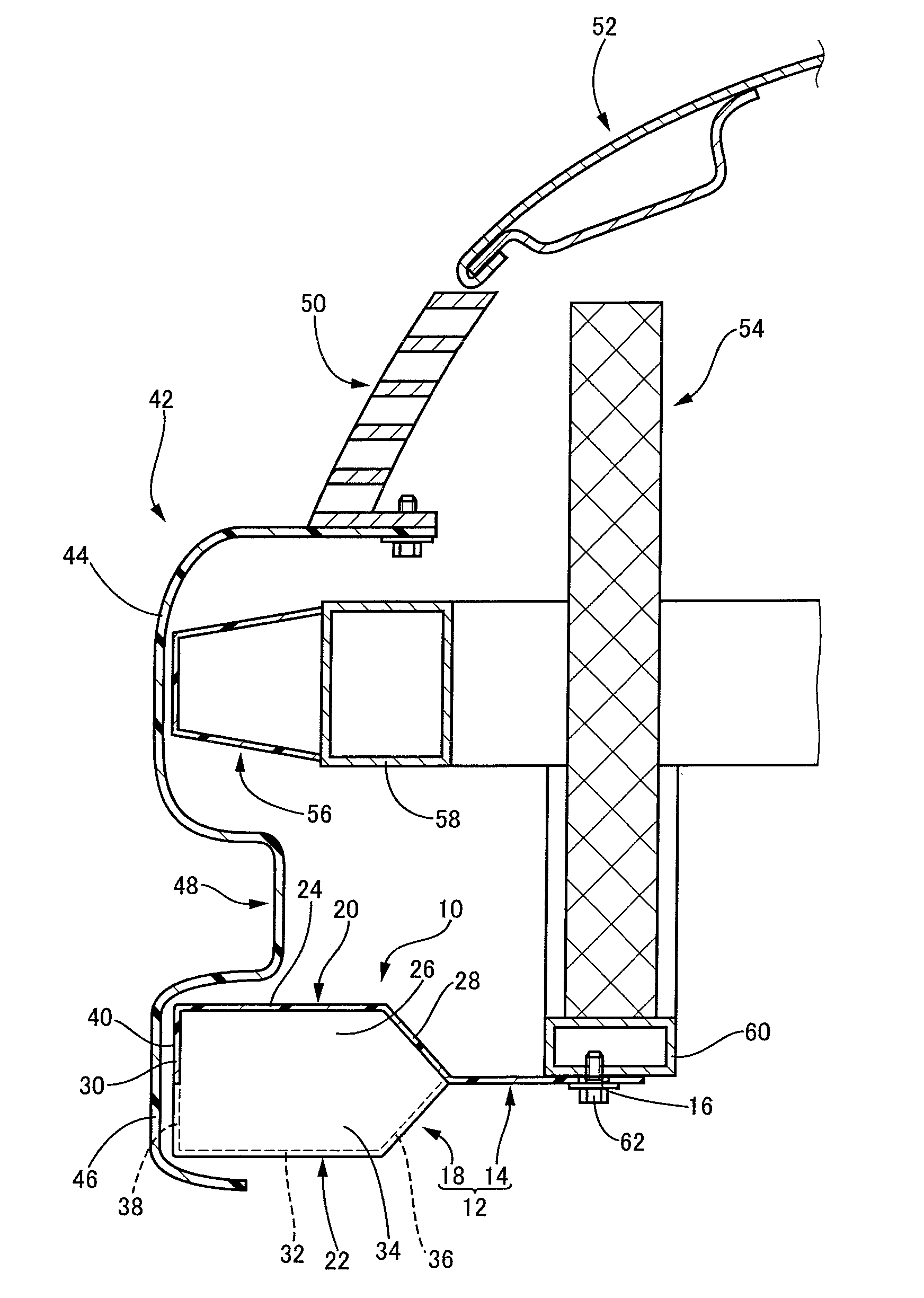
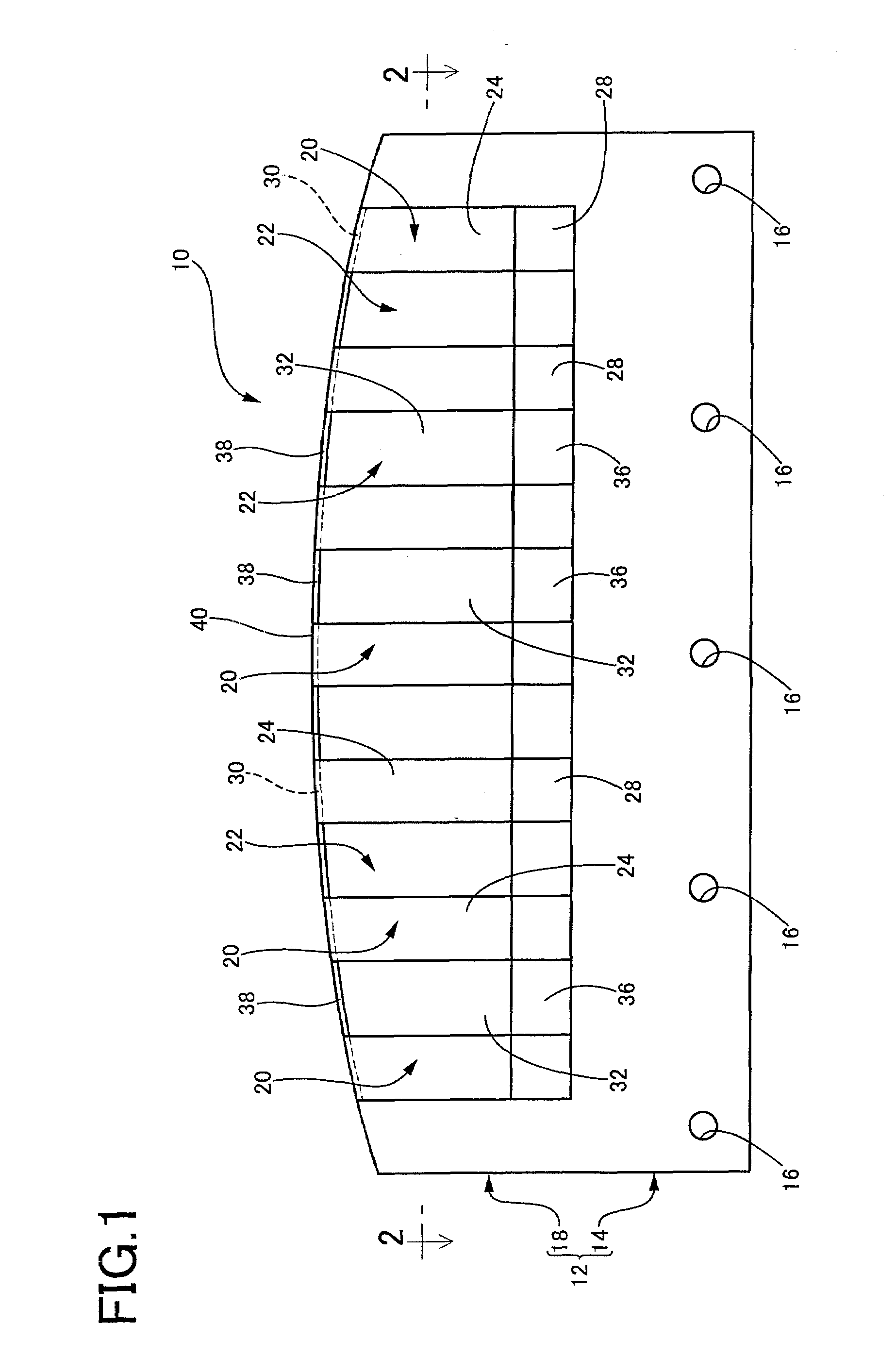
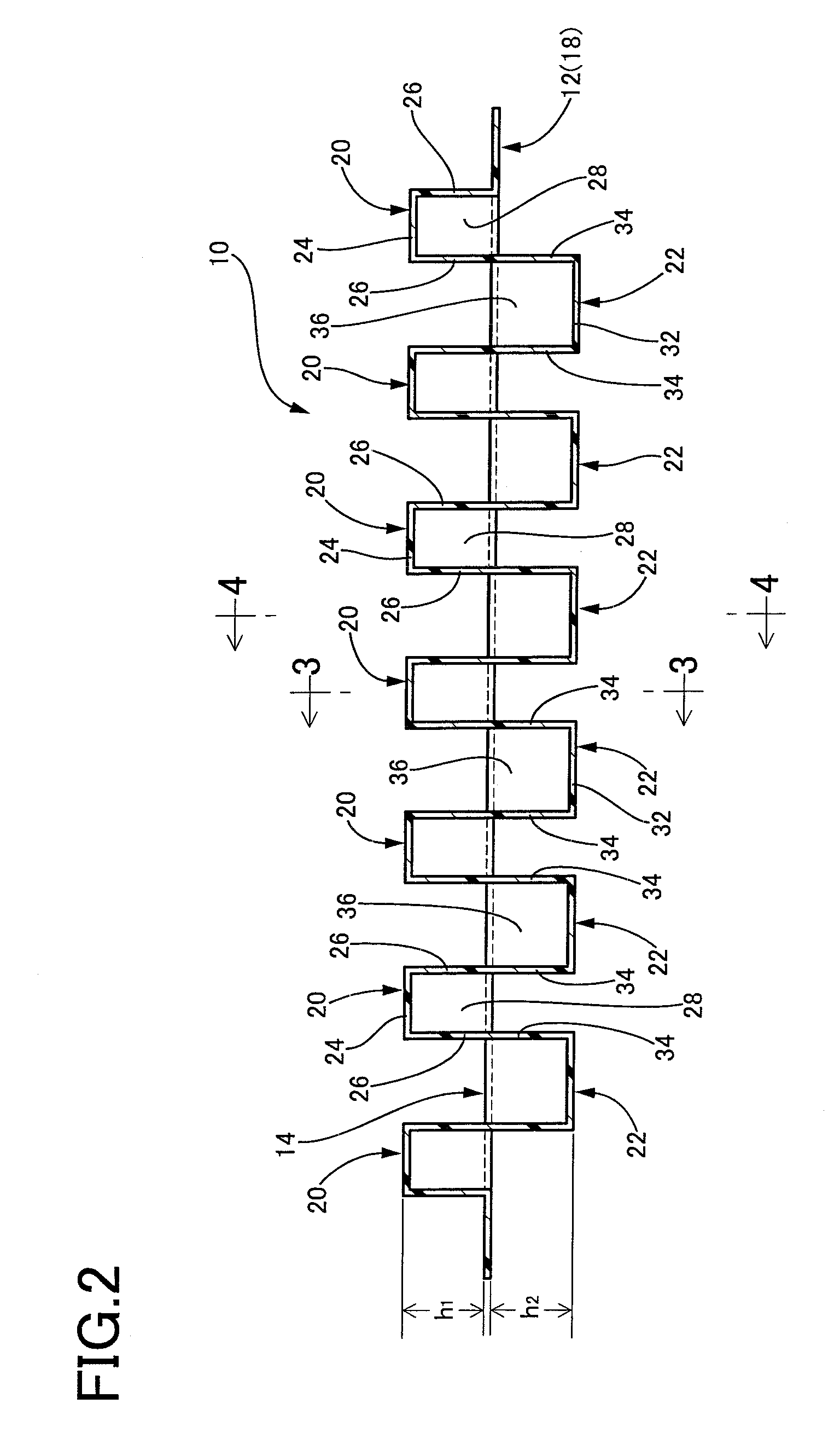
[0070]A representative example of the present invention will be described below in order to more clearly specify the characteristics of the invention. It should be noted that the present invention is not limited to the description of the example.

[0071]First, a leg-sweep apparatus having a configuration according to the present invention was prepared by carrying out injection molding using polypropylene, as shown in FIGS. 1 and 2. In this leg-sweep apparatus, the protrusion of first reinforcing beads from an upper surface of a reinforcing portion of a base plate and the protrusion of second reinforcing beads from a lower surface of the reinforcing portion has a height of 10 to 15 mm respectively, and the base plate has a thickness of 3 mm.

[0072]For comparison, apart from the invention apparatus indicated above, a leg-sweep apparatus having a configuration similar to that disclosed in the patent publication document 4 was prepared by carrying out injection molding using polypropylene....


PUM


Abstract

A pedestrian protection apparatus for a vehicle, includes a plate member which is disposed at a lower part of a front of the vehicle so as to extend in a frontward and backward direction of the vehicle, which includes a front portion and a rear portion; and a plurality of first reinforcing beads protruding upward and extending in the frontward and backward direction of the vehicle and a plurality of second reinforcing beads protruding downward and extending in the frontward and backward direction. The first reinforcing beads and the second reinforcing beads are provided integrally with the front portion so as to be alternately disposed in a vehicle width direction. The apparatus is arranged to sweep a leg portion that has collided with the front of the vehicle by contact of the plate member with the leg portion, thereby protecting the leg portion.

Description

[0001]The present application is based on Japanese Patent Application No. 2006-163174 filed on Jun. 13, 2006, the contents of which are incorporated herein by reference.BACKGROUND OF THE INVENTION[0002]1. Field of the Invention[0003]The present invention relates in general to a pedestrian protection apparatus for a vehicle, more particularly, to an improved structure of the pedestrian protection apparatus installed at a lower part of a front face of the vehicle and arranged to sweep a lower parts of the leg portion that has collided with or came into contact with the front face of the vehicle, thereby protecting the leg portion of the pedestrian.[0004]2. Discussion of Related Art[0005]Various types of protection apparatuses are conventionally installed at a front, a rear, or side faces of the vehicles such as automotive vehicles, mainly in order to absorb an impact energy generated upon a collision, for thereby protecting the bodies of the vehicles and vehicle passengers. In recent ...

Claims


Application Information

Patent Timeline
Patent Type & Authority Applications(United States)
IPC IPC(8): B60R21/00B60R19/12B60R19/16B60R19/18B60R19/54B60R21/34
CPCB60R19/18B60R2019/1866B60R21/34
Inventor HASEGAWA, KUNIAKIFUKUKAWA, MASANOBUOGURA, YOSHIHIRONOYORI, KEISUKEKUROKAWA, HIROKI
Owner KOJIMA PRESS IND CO LTD
Why Eureka
Try Eureka