
Multiwavelength smoke detector using white light LED

a multi-wavelength, led-based technology, applied in the field of photoelectric smoke detectors, can solve the problems of increasing the time needed for the smoke detector to react to some types of fire, unable to distinguish between light scattered from smoke (or aerosol) and light originating from the external environment, and unable to practically distinguish between smoke and smoke, etc., to achieve the effect of slowing down the air admittance and increasing the time needed for the smoke detector to react to fir

Inactive Publication Date: 2007-12-13
TYCO FIRE & SECURITY GMBH
View PDF16 Cites 4 Cited by
  • Summary
  • Abstract
  • Description
  • Claims
  • Application Information

AI Technical Summary

Benefits of technology

[0003] Due to the use of a single wavelength band, a system such as that described above cannot practically distinguish between smoke due to an unwanted fire and aerosols generated by numerous harmless activities such as cooking and bathing. Such a system is also unable to distinguish between light scattered from smoke (or aerosol) and light originating from the external environment. Therefore, the smoke chamber is typically separated from the external environment by a set of light baffles, commonly referred to as a “labyrinth,” which exclude ambient light but admit air and smoke. However, the labyrinth tends to slow the admittance of air and smoke to the smoke chamber, thus increasing the time needed for the smoke detector to react to some types of fires.
[0005] It is anticipated that the spectrally-resolved scattered and transmitted light intensities measured by this invention will enable it to distinguish between different types of smoke and other aerosols thereby providing a means for substantially reducing the effect of many common nuisance alarm sources. It is also expected that the invention will be inherently less sensitive to external light sources than is typical at present. This will allow the use of light baffles with reduced resistance to smoke entry thus resulting in faster detector response times to some fires.
[0010] The present invention, on the other hand, employs a single LED that emits white light, i.e., spectrally broad light, to provide multiple wavelength illumination. The use of a single white light LED as the light source is advantageous in that it reduces parts count, energy consumption (possibly), and the minimum required size of the smoke detector.
[0012] The present invention, on the other hand, uses a continuous spectral distribution over the entire visible range (and potentially beyond, depending on availability of components). This approach can potentially yield much more information than what can be obtained from Runciman's limited number of discrete wavelengths.
[0013] Finally, while Runciman teaches the use of either multiple detectors with different spectral sensitivities or a single detector alternately illuminated by different wavelengths, an embodiment of the present invention uses a single, multi-band photodetector to spectrally resolve the scattered white light. Compared to using multiple photodetecting elements, the use of a single photodetector that generates independent output signals for different spectral bands has the advantage of reducing parts count (and cost) as well as the minimum required size of the smoke detector.
[0015] An analyzer determines, based on the measured light intensities of the different wavelength bands, whether a dangerous smoke / fire condition is present. In at least one embodiment, the analyzer estimates, responsive to the measured light intensities, a size distribution of an aerosol, for example by using an inversion algorithm based on equations for Mie scattering. Alternatively, the analyzer may compare the measured light intensities with previously measured and stored intensity data (i.e., spectral signatures) for at least one aerosol of known composition. The analyzer can also reduce inherent sensitivity to external ambient light.

Problems solved by technology

Due to the use of a single wavelength band, a system such as that described above cannot practically distinguish between smoke due to an unwanted fire and aerosols generated by numerous harmless activities such as cooking and bathing.
Such a system is also unable to distinguish between light scattered from smoke (or aerosol) and light originating from the external environment.
However, the labyrinth tends to slow the admittance of air and smoke to the smoke chamber, thus increasing the time needed for the smoke detector to react to some types of fires.

Method used


Image

  • Multiwavelength smoke detector using white light LED
  • Multiwavelength smoke detector using white light LED
  • Multiwavelength smoke detector using white light LED

Examples


Embodiment Construction

[0030] A description of preferred embodiments of the invention follows.

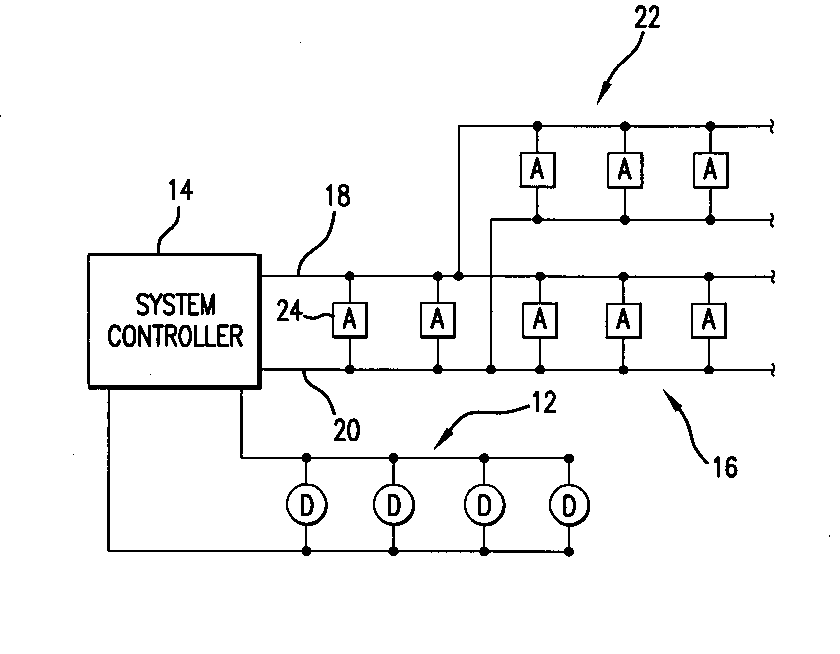
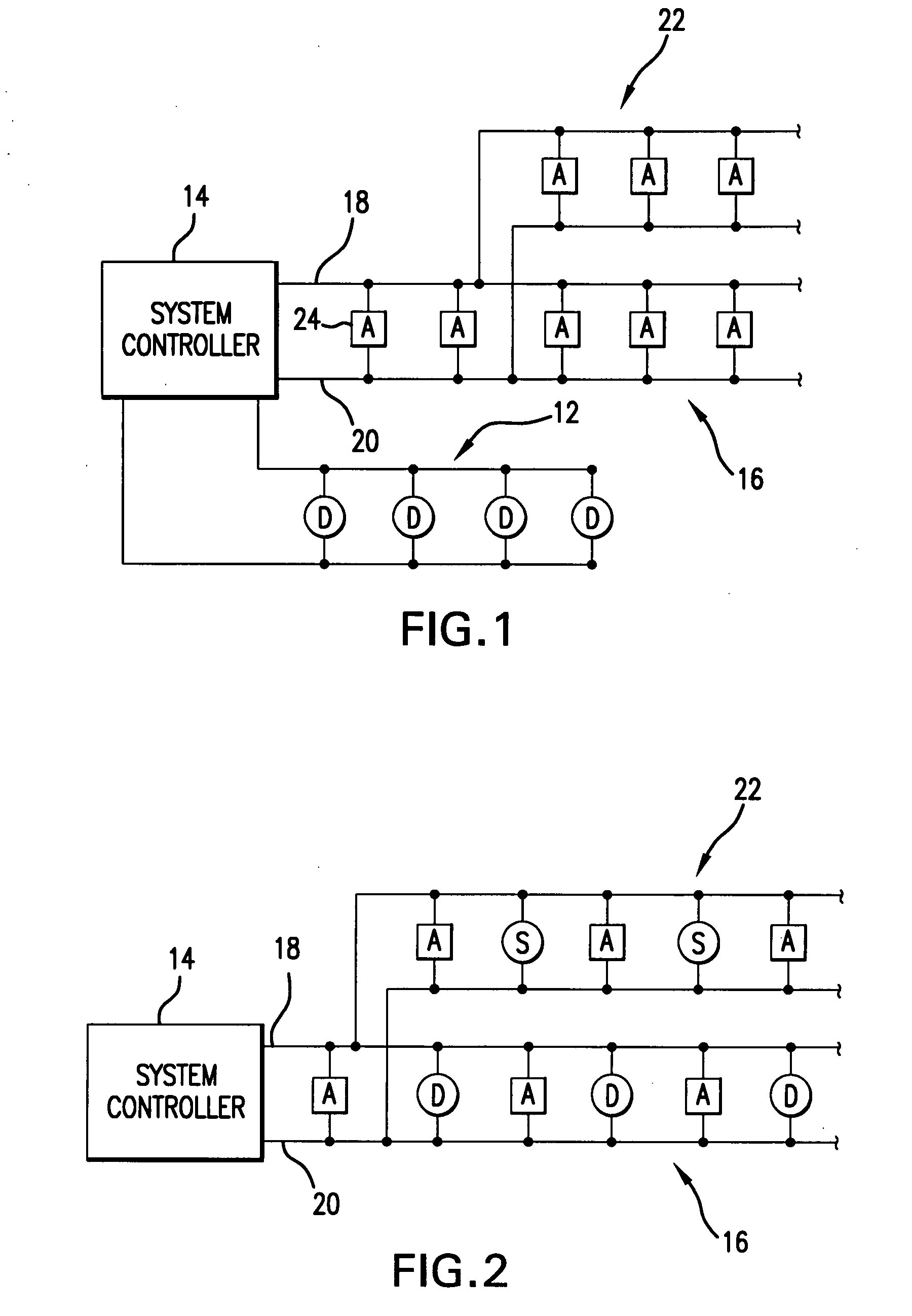
[0031] A system embodying the present invention is illustrated in FIG. 1. As in a conventional alarm system, the system includes one or more detector networks 12 having individual alarm condition detectors D which are monitored by a system controller 14. When an alarm condition is sensed, the system controller 14 signals the alarm to the appropriate devices through at least one network 16 of alarm notification appliances A, which may include, for example, a visual alarm (strobe), an audible alarm (horn), a speaker, or a combination thereof.

[0032] As shown, all of the notification appliances are coupled across a pair of power lines 18 and 20 that advantageously also carry communications between the system controller 14 and the notification appliances 24.

[0033]FIG. 2 illustrates an alternative embodiment of the present invention wherein the detectors D are placed on the same NAC 16 as the notification appliances...


PUM


Abstract

A smoke detector includes a smoke detection chamber containing a white light LED and a light detector. The light detector detects light within at least two distinct optical wavelength bands, and generates respective signals indicative of the intensities of the detected light. An analyzer determines, based on the measured light intensities of the different wavelength bands, whether a dangerous smoke / fire condition is present.

Description

RELATED APPLICATION(S) [0001] This application claims the benefit of U.S. Provisional Application No. 60 / 502,339, filed Sep. 12, 2003. The entire teachings of the above application(s) are incorporated herein by reference.BACKGROUND OF THE INVENTION [0002] Conventional photoelectric smoke detectors use a single LED operating at a single narrow wavelength band to illuminate a volume commonly referred to as the smoke chamber. Typically, a single light detector is arranged so that light from the LED is detected only when it is scattered out of its direct path due to the presence of smoke or some other aerosol. SUMMARY OF THE INVENTION [0003] Due to the use of a single wavelength band, a system such as that described above cannot practically distinguish between smoke due to an unwanted fire and aerosols generated by numerous harmless activities such as cooking and bathing. Such a system is also unable to distinguish between light scattered from smoke (or aerosol) and light originating fr...

Claims


Application Information

Patent Timeline
Patent Type & Authority Applications(United States)
IPC IPC(8): G08B17/10G08B17/107
CPCG08B17/107
Inventor QUALEY, JAMES R. III
Owner TYCO FIRE & SECURITY GMBH
Learn More