Forced air cooled electrical box for mining equipment

Inactive Publication Date: 2007-12-13
ALLIANCE COAL LLC
View PDF12 Cites 31 Cited by
  • Summary
  • Abstract
  • Description
  • Claims
  • Application Information

AI Technical Summary

Benefits of technology

[0005]In accordance with the purposes of the present invention as described herein, an electrical box is provided. The electrical box comprises a housing including an explosion proof enclosure and a cooling duct. An electrical circuit is held in the enclosure. The electrical box further includes a fan

Problems solved by technology

An unfortunate by-product of all this fl

Method used


Image

  • Forced air cooled electrical box for mining equipment
  • Forced air cooled electrical box for mining equipment
  • Forced air cooled electrical box for mining equipment

Examples


Embodiment Construction

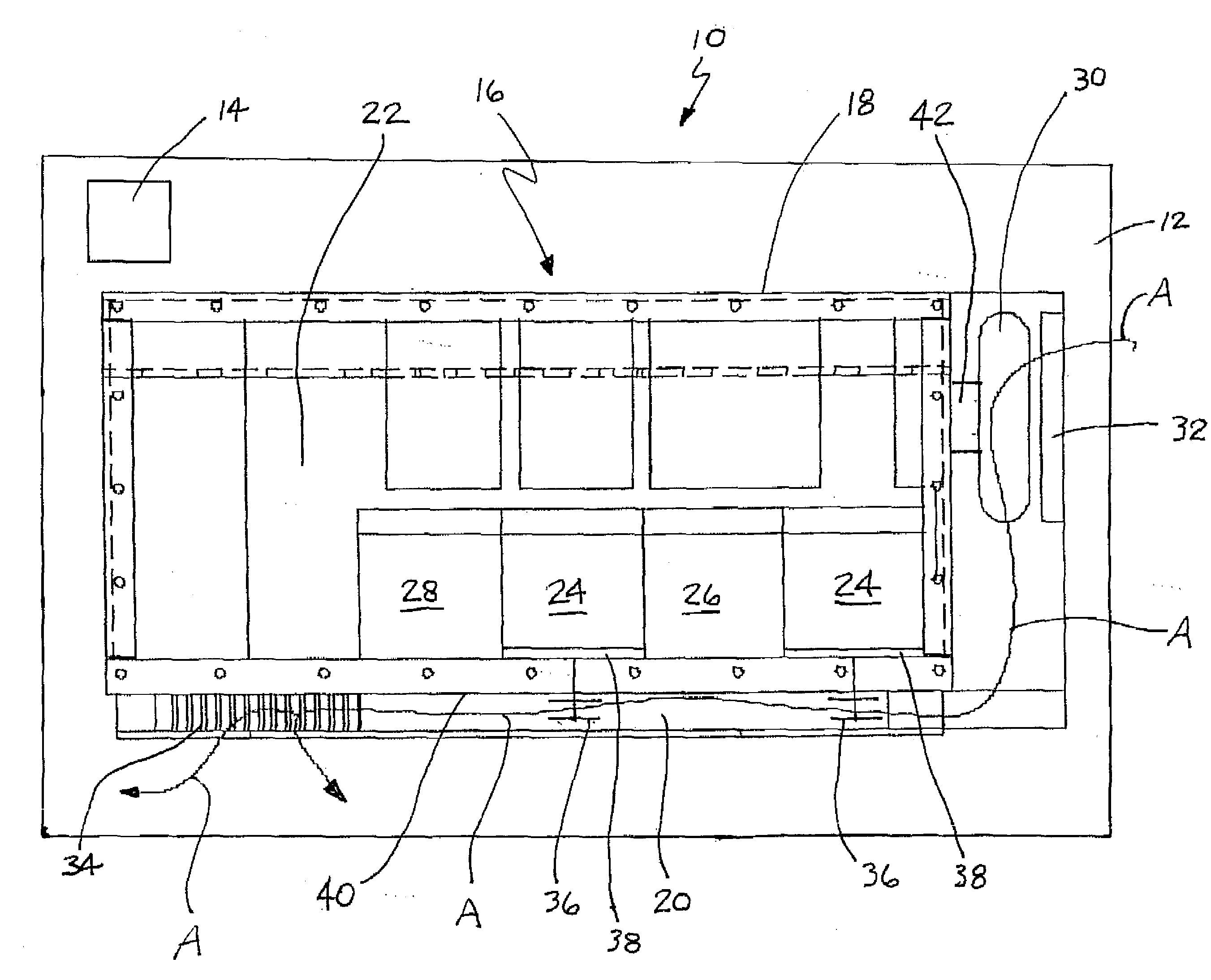
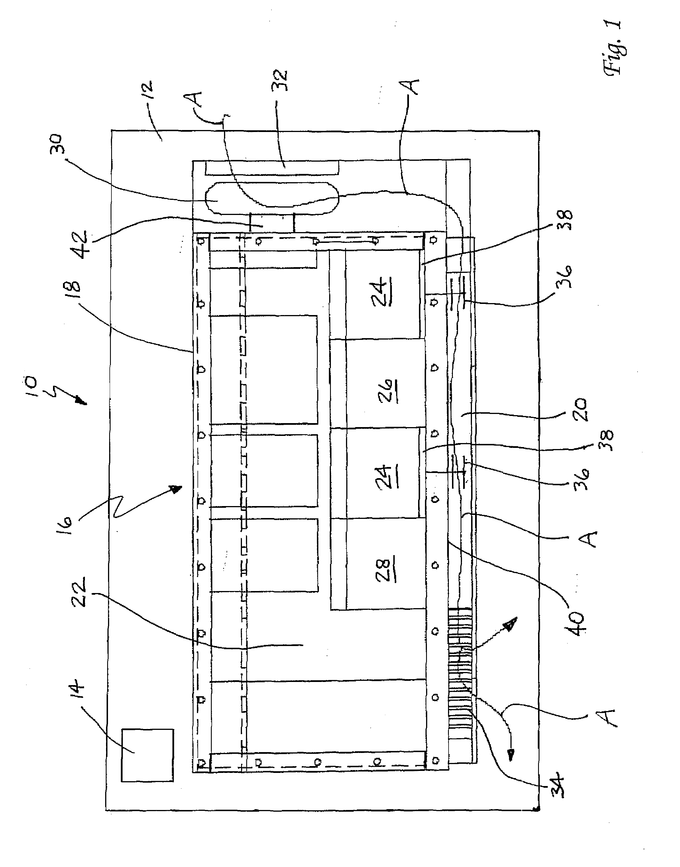
[0014]Reference is now made to FIG. 1 which schematically illustrates a mining apparatus 10 such as a mine locomotive, roof bolting machine, mobile conveyor, shuttle car, scoop tractor, continuous miner or the like. The mining apparatus 10 comprises a body 12 that carries an electric drive motor 14 such as a conveyor drive motor, traction drive motor or the like. The body 12 further includes an electrical box 16 including an explosion proof enclosure 18 and a cooling duct 20. The explosion proof enclosure 18 is made in accordance with engineering specifications as set forth in Title 30 C.F.R. § 18.31. The compartment 22 defined by the explosion proof enclosure 18 houses electrical circuits for various systems of the apparatus 10. These include, for example, a tractor drive circuit 24, a pump circuit 26 for the hydraulic system and a motor circuit 28 for driving a conveyor.

[0015]A fan 30 is mounted in the electrical box 16 adjacent the explosion proof enclosure 18. The fan 30 draws a...


PUM


Abstract

An electrical box for mining apparatus and a mining apparatus are provided. The electrical box includes a housing having an explosion proof enclosure and a cooling duct. An electrical circuit is held in the enclosure. A fan is provided for forcing air through the cooling duct.

Description

[0001]This application claims priority to prior U.S. Provisional Patent Application Ser. No. 60 / 812,748 filed 12 Jun. 2006.TECHNICAL FIELD[0002]The present invention relates generally to the mining equipment field and, more particularly, to a forced air-cooled electrical box for mining equipment.BACKGROUND OF THE INVENTION[0003]Mine locomotives, mobile conveyors, roof bolting machines, scoop tractors, shuttle cars, continuous miners, other mining vehicles and even stationary mining equipment generally rely upon electrical power systems based on alternating current (AC) or direct current (DC). Such mining equipment often utilizes powerful electrical motors which draw a great deal of current through the electrical circuits of the equipment. An unfortunate by-product of all this flowing current is the production of heat. In order to insure proper operation of this equipment, this heat must be efficiently dissipated.[0004]The present invention relates to a forced air-cooled electrical b...

Claims


Application Information

Patent Timeline
IPC IPC(8): H05K7/20
CPCH05K9/0015H05K7/20163
Inventor WATSON, MARK A.WATSON, ROBERT E.
Owner ALLIANCE COAL LLC
Why Eureka
Try Eureka