[0010]This invention overcomes disadvantages of the prior art by providing a portable combustion device that provides a cleaner combustion, reduces the kindling period, and provides a more efficient overall combustion through the use of a fan that directs a predetermined volume of
airflow over the combustible fuel—typically wood or similar
cellulose-based biological solids. The direction of
airflow is accomplished without the need for canister fuels or external power sources using the stove's own generated heat with the aid of a
thermoelectric generator (TEG) and novel heat sink arrangement to generate
electricity that powers the fan, and drives the airflow.
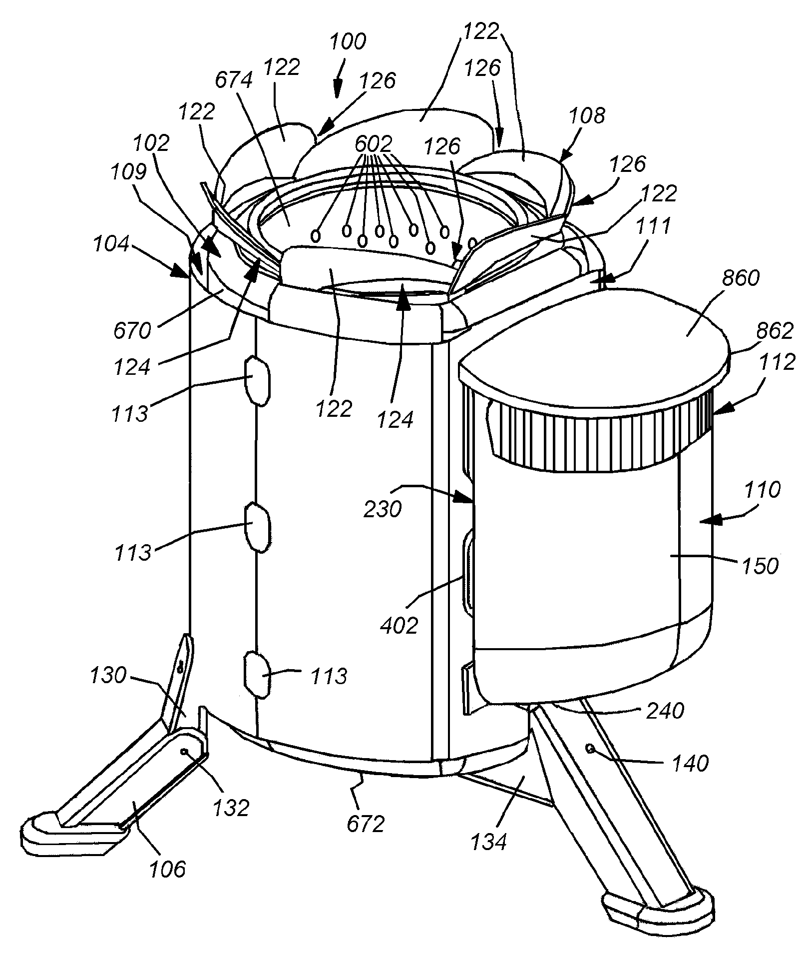
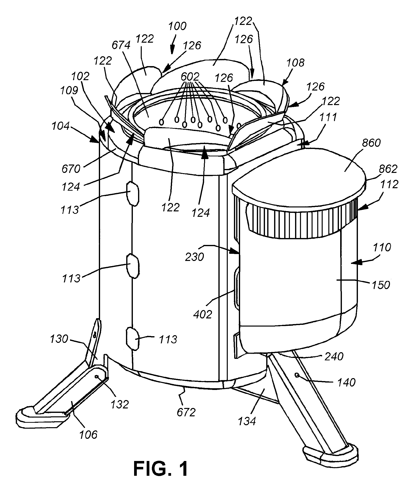
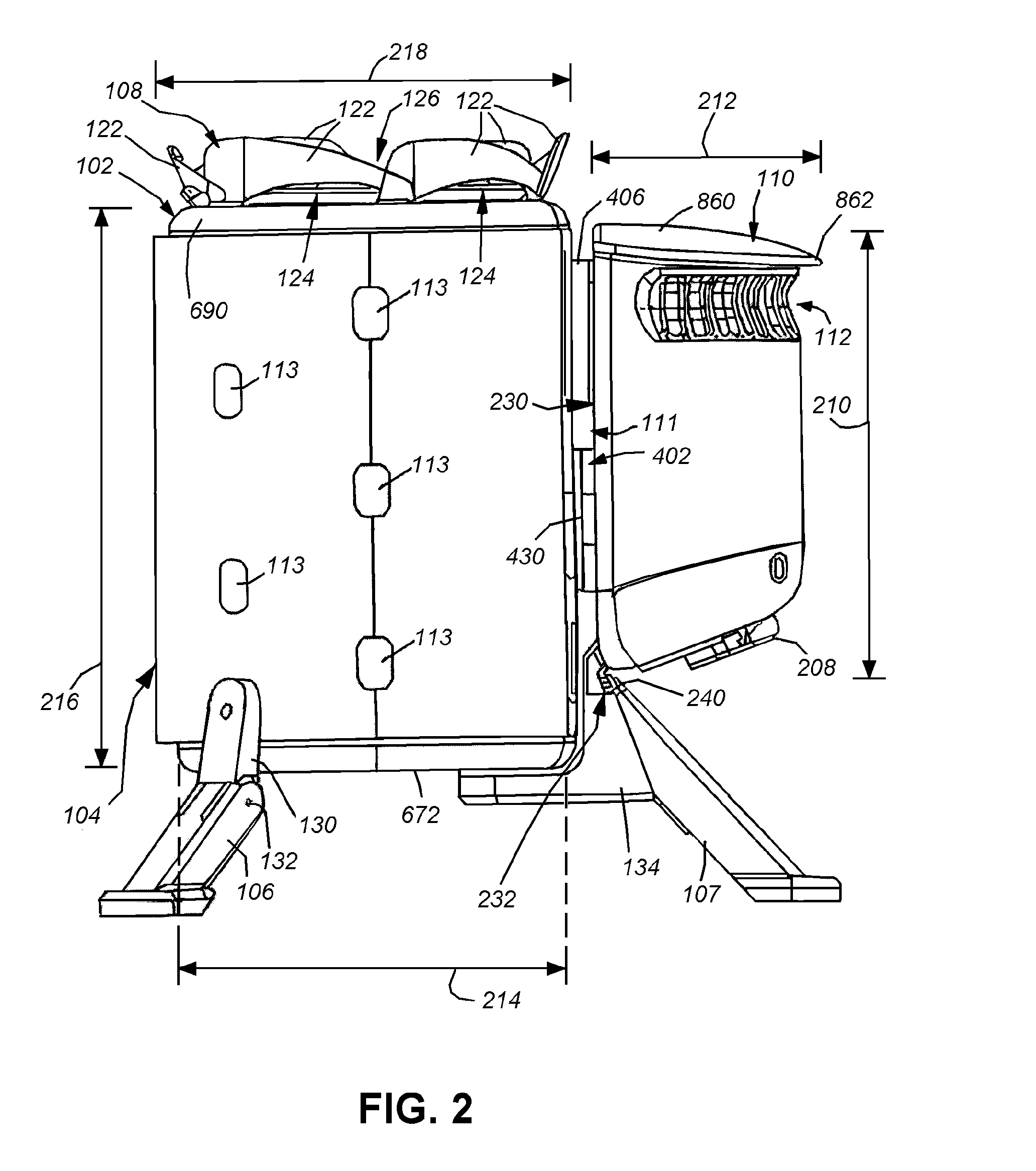
[0011]In an illustrative embodiment, the combustion device has a combustion chamber into which the fuel source is placed for combustion. Mounted to the wall (for example along a side) of the combustion chamber is a housing that encloses the TEG, which generates an electrical output based on a difference in temperature on opposing sides (a “hot side” and a “
cold side”) of the thermoelectric device, wherein the larger the differential, the larger the electrical output. Mounted onto the TEG housing and protruding into the combustion chamber through a small passageway is a heat-conducting probe and heat-conducting probe base unit. The heat-conducting probe is constructed from a material capable of efficiently transferring the heat generated in the combustion chamber to the heat-conducting probe base, which is in contact with the hot side of the TEG device. On the opposing
cold side, the TEG is also in contact with a heat sink having a plurality of independent vanes extending from the base, which is designed to remove heat from the TEG device through interaction with
ambient air that passes over the vanes from a port located along the side of the TEG housing. Additionally, the TEG housing has a motor and a airflow driver in the form of a fan (for example an axial
centrifugal fan that employs moving blades, vanes or the like to drive air) near the heat sink to further draw air away from the heat sink and / or blow
ambient air through the heat sink into the combustion chamber (depending in part upon where the airflow driver(s) is / are located with respect to the heat sink) and aid in the cooling of the heat sink, and to force air onto the combusting fuel through a plurality of
peripheral ports that connect with an
air space located between the inner and outer walls of the combustion chamber. This arrangement thereby affords the fan-driven airflow the
dual purpose of cooling the
cold side of the TEG to create a higher heat differential between it and the hot side of the probe and oxidizing the burning fuel, while also insulating the TEG housing from the hot inner walls of the inner
flame-contacting part of the combustion chamber.
[0012]As the fuel is combusted within the combustion chamber, heat is produced. The heat creates a difference in temperature between the sides of the TEG, thus producing an
electrical current output. As the temperature rises, the heat sink cools the device on the opposing side of the TEG creating an even larger temperature differential, and in turn, creating a larger electrical output. This electrical output is transmitted to the motor that is driving the fan, which in turn, draws or blows cooler ambient air across the heat sink thus promoting more efficient,
oxygen-rich combustion of the fuel. This cycle essentially creates a
feedback loop, which quickly increases the efficiency of the combustion once it begins. This cycle also expedites the kindling cycle, because the
heat conducting probe can be placed where the
flame is initially lit, thereby allowing airflow to begin when even a low temperature differential is experienced by the TEG.
[0013]Moreover, the airflow driver draws or blows outside air into the TEG housing to further cool down the heat sink by drawing cooler outside air across it, as well as drawing the air near the heat sink away from the heat sink. This will cool one side of the TEG device creating a larger temperature differential, which will increase the electrical output to
drive motor and fan structure, which will continue to draw more into the TEG housing. Additionally, any surplus
electricity from the TEG can be used as part of a
cogeneration system to power a charging
system for a variety of electrical or electronic devices having appropriate
power consumption levels relative to the available
heat energy. Such devices can include, for example a radio, light or cellphone charger. Additionally, the airflow driver draws or blows the ambient air from the heat sink and forces the air into the combustion chamber creating more turbulence within the chamber insuring a more efficient combustion. All of these components provide a
system that promotes a portable or stationary combustion device which is capable of using
biomass fuels that does not require canisters or an external power supply. The invention thereby provides a cleaner burning of
biomass fuels, and the use of the TEG device in this configuration ensures a quicker kindling period as well as more efficient combustion. More particularly, the placement of the TEG and its heat-conducting probe, so as to receive optimized
heat transfer from the
flame and thereby more quickly heat the TEG, ensures quicker operation of the fan / airflow driver, and obviates the need for a startup battery. Additionally, the
heat conducting probe defines a conduit for conducting heat from a remote flame or heat source. This discrete heat conduit enables a variety of many flexible design configurations where the TEG and airflow driver can be placed on the outside surface or remotely from (and typically near) any combustion device such as biomass stoves, barbeques, grills, camp fires,
butane,
alcohol and
propane burners, and any other source of open flame and / or heat
convection (for example a heated airflow).

