Gaseous fuel burner

Active Publication Date: 2005-11-10
NEW POWER CONCEPTS
View PDF99 Cites 63 Cited by
  • Summary
  • Abstract
  • Description
  • Claims
  • Application Information

AI Technical Summary

Benefits of technology

[0007] Accordingly, in various embodiments of the invention, we provide a gaseous fuel burner comprising an ejector with fuel supply, a blower, a combustion chamber and a heat exchanger, to address the challenges facing the existing burners. Certain embodiments of this gaseous fuel burner are capable of using low static pressure gaseous fuel without any substantial additional equipment or energy demands. Certain embodiments of the invention can maintain an approximately st

Problems solved by technology

Furthermore, the gaseous fuel burner may have multiple fuel restrictions out

Method used


Image

  • Gaseous fuel burner
  • Gaseous fuel burner
  • Gaseous fuel burner

Examples


Embodiment Construction

[0025] Definitions: As used in this description and the accompanying claims, the following terms shall have the meanings indicated, unless the context otherwise requires: Fuel-Air Equivalence ratio (φ)=Actual Fuel-Air Mass Ratio / Stoichiometric Fuel-Air Mass Ratio. The stoichiometric fuel-air mass ratio is defined as the mass ratio needed to balance the fuel+air chemical equation. The stoichiometric fuel-air mass ratio is well known for common fuels such as propane (0.0638 g fuel / g air) and calculable for gases such as biogas.

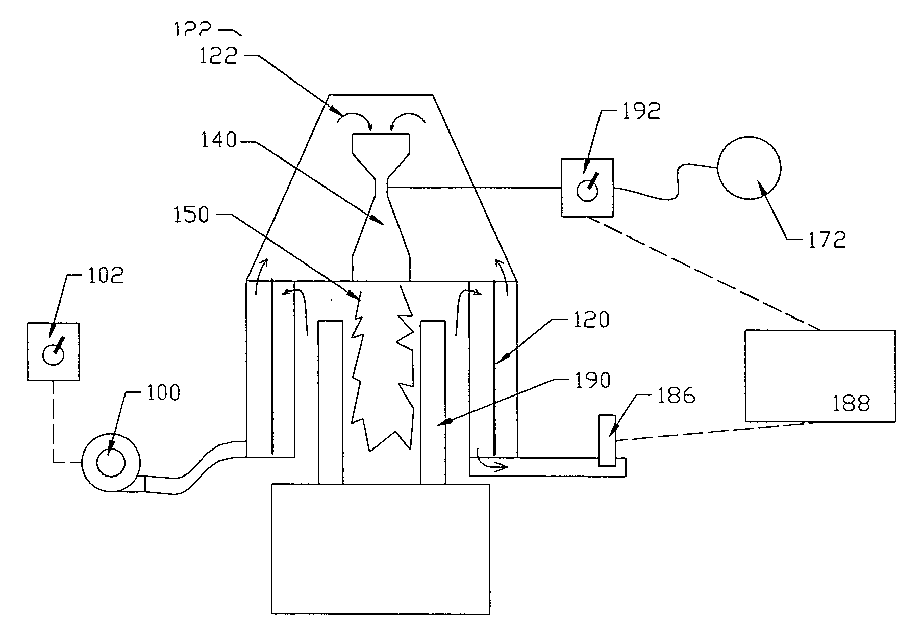
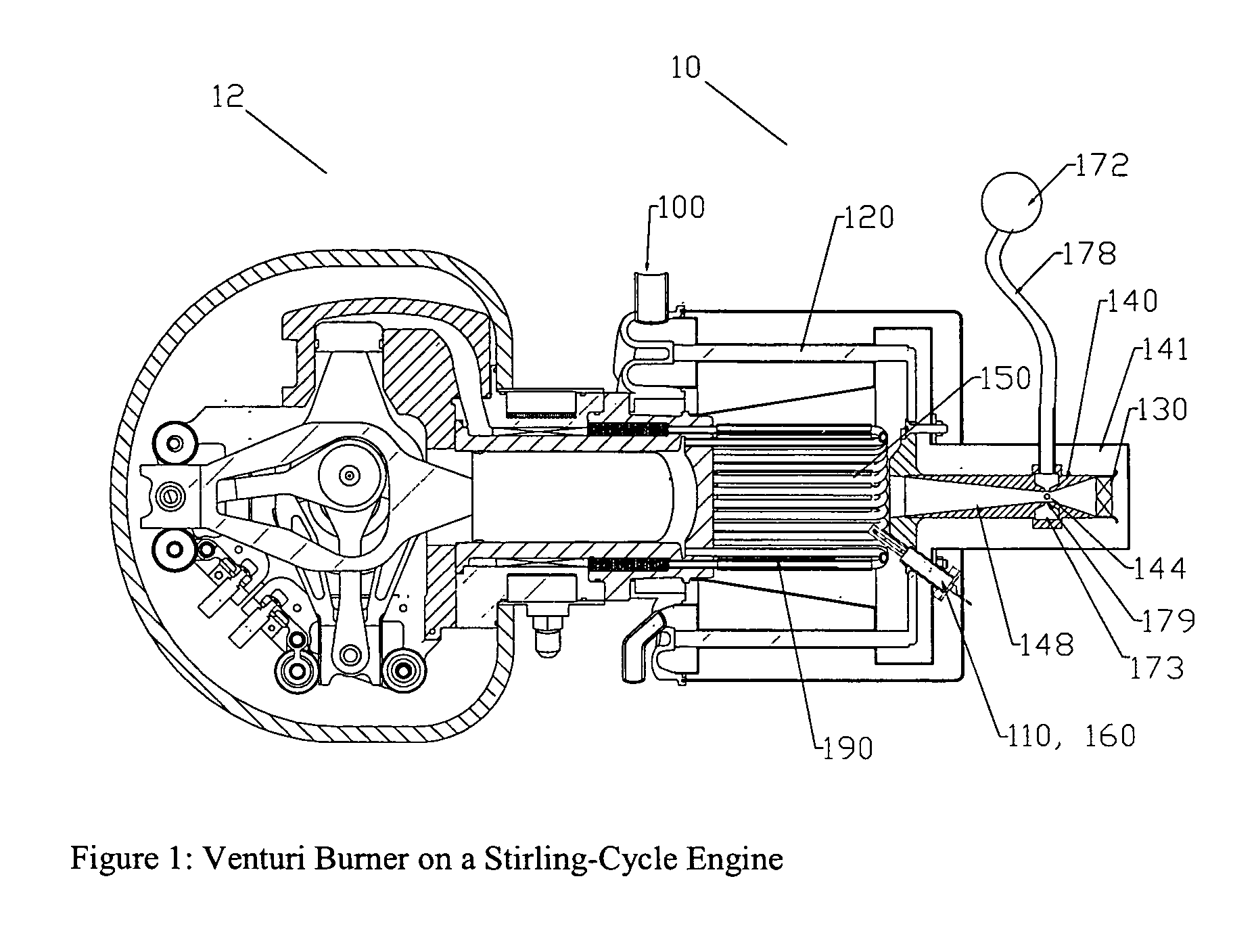
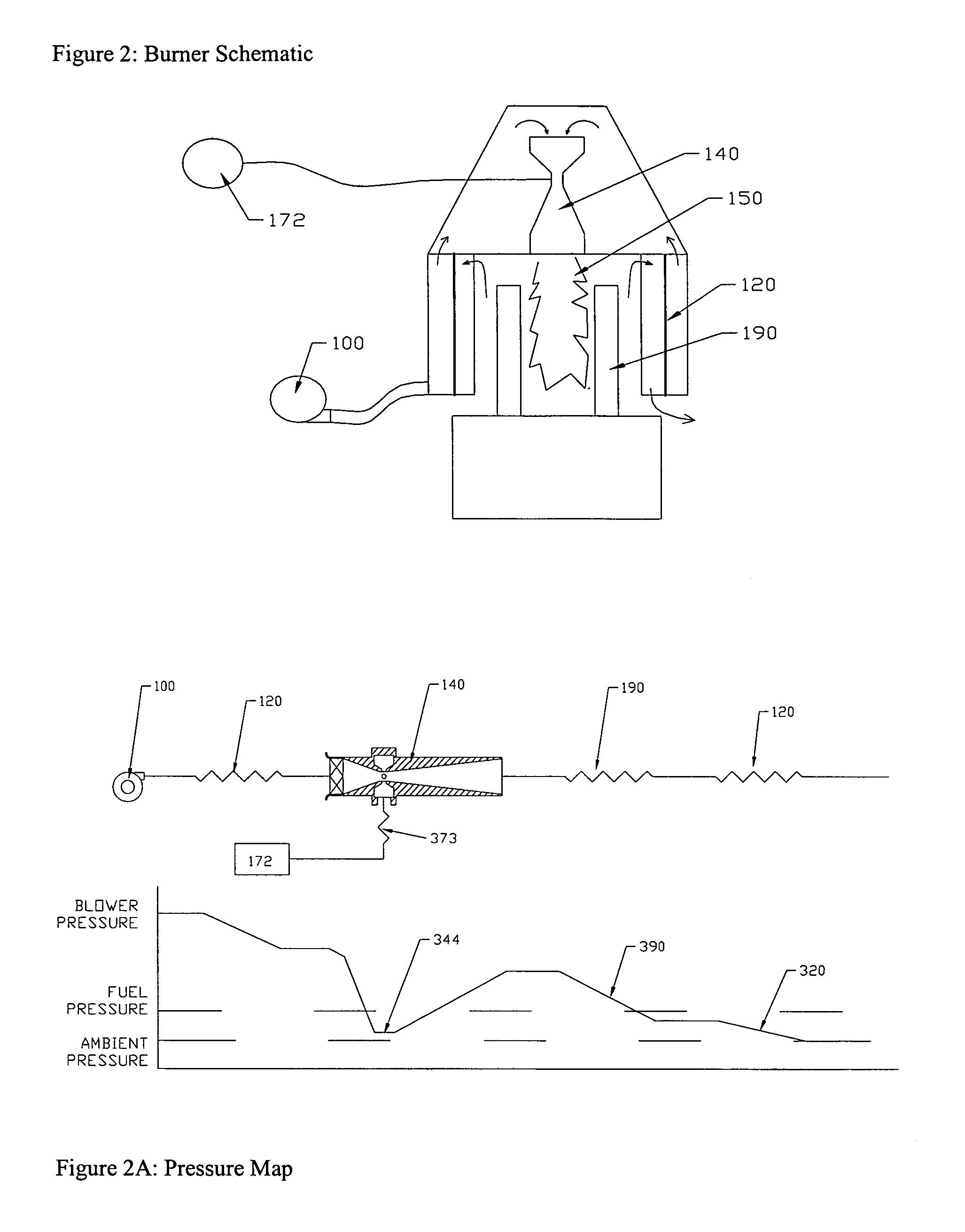
[0026]FIG. 1 illustrates an embodiment of the invention in the exemplary application of a gaseous fuel burner system as a gaseous fuel burner 10 for a Stirling cycle engine 12. Although, this embodiment of the invention is described specifically in the context of a Stirling cycle engine, embodiments of the invention are not limited to such applications. Those skilled in the art will appreciate that the present invention may have application in other systems, su...


PUM


Abstract

An ejector, such as a venturi, facilitates the delivery of gaseous fuel to the combustion chamber of a burner. A blower forces air through the ejector, and the air flow produces a suction that draws fuel from a fuel inlet to produce a fuel-air mixture. The amount of fuel drawn from the fuel inlet is a function of the air flow such that a substantially constant fuel-air ratio is obtained over a range of air flow rates and temperatures without the need for a separate high-pressure fuel pump. The fuel-air mixture may be provided to a combustion chamber for combustion. Air from the blower may be pre-heated prior to entering the ejector, for example, using a heat exchanger that recovers some of the heat from the combusted fuel-air mixture. Air flow through the ejector may be conditioned, for example, by a swirler, to produce a tangential air flow that can increase fuel flow by increasing air velocity across the fuel inlet and/or produce a swirl-stabilized flame in the combustion chamber. The combusted fuel-air mixture may be provided to a thermal load, such as an external combustion engine. Blower speed may be controlled manually or automatically to control power output. Fuel flow to the ejector can be controlled manually or automatically to control fuel-air ratio. The burner can be configured to operate with multiple fuel types, for example, using a fuel selector with fixed or variable restrictors.

Description

PRIORITY [0001] This application claims priority from U.S. Provisional Patent Application No. 60 / 568,629 entitled Gaseous Fuel Burner, filed on May 6, 2004 in the names of Kurt L. Kornbluth and Michael G. Norris, which is hereby incorporated herein by reference in its entirety.TECHNICAL FIELD [0002] The present invention relates to systems, methods, and apparatus for combusting fuel and air in a burner, more particularly for a gaseous fuel burner that uses an ejector and a heat exchanger to combust gaseous fuels in a system including an external combustion engine having a heater head. BACKGROUND [0003] A burner that supplies high temperature gases to a process or an external combustion engine should have high thermal efficiency, low emissions, good cold starting capabilities and a large turndown ratio or wide dynamic range. High thermal efficiency may be achieved by capturing the thermal power in the hot exhaust exiting the load-heat-exchanger. For example, in a Stirling engine, the...

Claims


Application Information

Patent Timeline
IPC IPC(8): F23C7/00F23D14/04F23D14/34F23D14/60F23D14/64F23D14/66F23D14/72F23D17/00F23D99/00F23L15/02F23L15/04F23N1/00F23N3/08F23N5/00
CPCF23C7/004F23N2033/08F23D14/34F23D14/60F23D14/64F23D14/66F23D14/725F23D17/00F23D99/003F23D2204/00F23L15/02F23L15/04F23N3/082F23N5/003F23N5/006F23D14/04F23D91/02F23N2233/08Y02E20/34
Inventor KORNBLUTH, KURT L.NORRIS, MICHAEL G.
Owner NEW POWER CONCEPTS
Why Eureka
Try Eureka