Compact surface self-compensated hydrostatic bearings

a self-compensation, bearing technology, applied in the direction of bearings, linear bearings, shafts and bearings, etc., can solve the problems of increasing cost, time-consuming and labor-intensive to adjust all the restrictors, and adding complexity and cost to designs

Active Publication Date: 2007-12-13
AMETEK PRECITECH
View PDF13 Cites 15 Cited by
  • Summary
  • Abstract
  • Description
  • Claims
  • Application Information

AI Technical Summary

Benefits of technology

[0008]Accordingly, the present invention provides a surface self compensated hydrostatic bearing for use in precision machine tools, having, in combination, a rotor assembly, a stator assembly attached to a machine bed, a fluid pressure source and distribution system to supply pressurized fluid to keep the rotor assembly from making physical contact with the stator assembly.

Problems solved by technology

Also, because, capillary resistance, for example, varies with the fourth power of the diameter, tuning all the restrictors can be time consuming.
Further, because one restrictor is required for each bearing pocket, including as many bearing pockets as possible in order to enhance averaging and improve accuracy greatly increases cost.
Alternatively, elastically deforming elements were also used to tune the compensation, but these designs add complexity and cost.
On the other hand, the rest of the machine structure is not infinitely stiff, and a valve on every pocket can become very expensive very quickly.
Thus, this attempt to improve self-compensated bearings is also not without its drawbacks.
Moreover, the previous self-compensation designs required cross-drilling or the use of external fluid lines to connect the compensator to the opposed pad.
These designs, however, still do not lend themselves to low profile rotary tables, and hence angular surface self-compensated rotary bearings were initially developed.

Method used


Image

  • Compact surface self-compensated hydrostatic bearings
  • Compact surface self-compensated hydrostatic bearings
  • Compact surface self-compensated hydrostatic bearings

Examples


Embodiment Construction

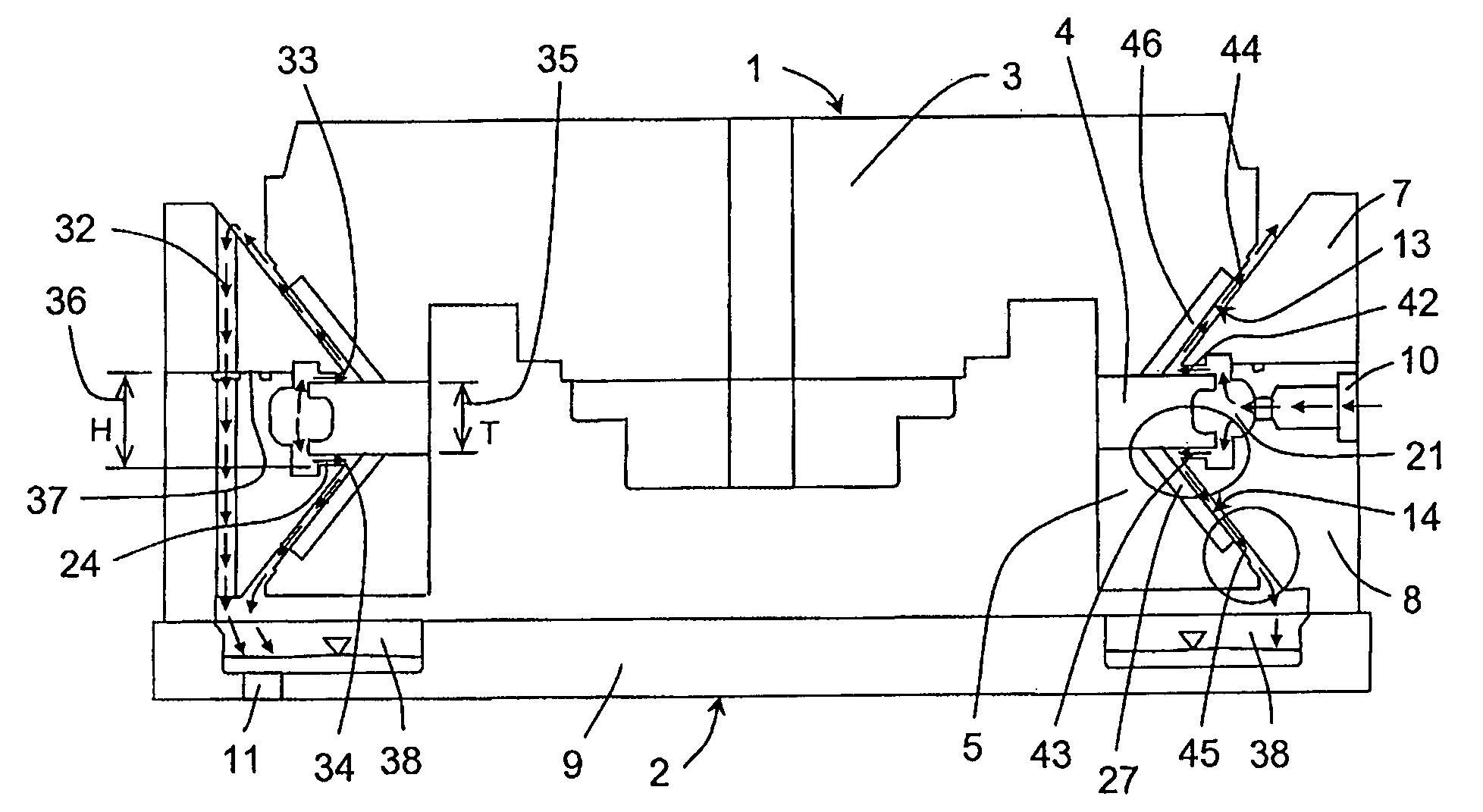
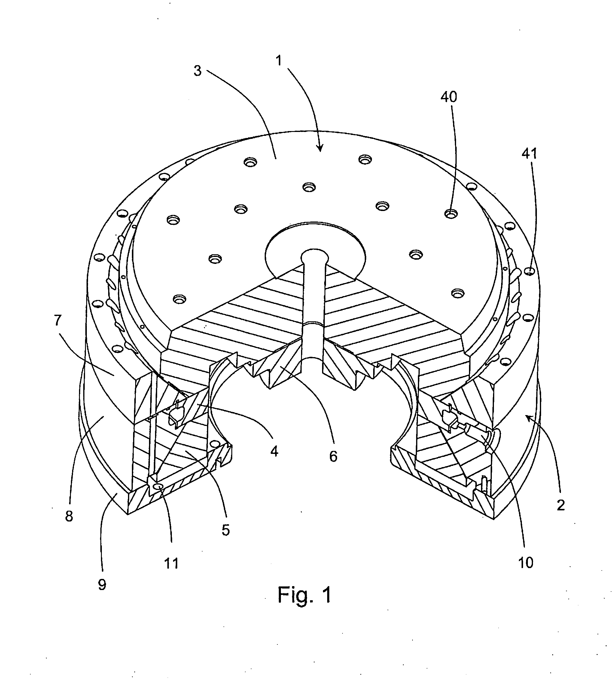
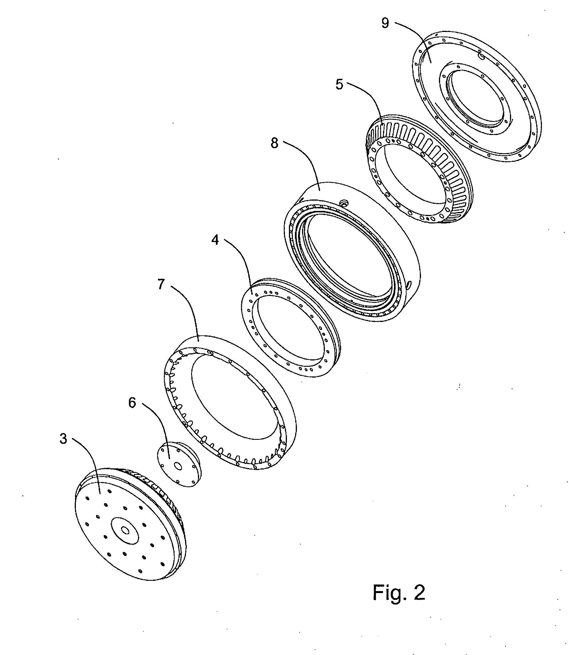
[0028]The present invention relates to a rotary hydrostatic bearing system for use in precision machine tools, having, in combination, a rotor assembly, a stator assembly attached to a machine bed, a fluid pressure source and distribution system to supply pressurized fluid to keep the rotor assembly from making physical contact with the stator assembly.

[0029]In the present invention, flow restriction, or compensation, between the pressure supply and the load supporting surfaces is provided by a geometry that is an integral part of the system formed onto components that make up the assembly. In particular, the geometry is especially well suited for use in spindles and rotary tables, but it can also be used for linear motion systems. The invention establishes the relative position of a rotor assembly to a stator assembly with the use of a novel arrangement of precision surfaces, which result in a highly rigid and stable hydrostatic bearing, particularly in axial and tilt modes of load...


PUM


Abstract

A compact surface self-compensated hydrostatic bearing includes a rotor assembly including a rotor plate having upper and lower fluid restricting faces, a rotor top and bottom, each having bearing surfaces angled with respect to an axis of rotation of the rotor assembly; a stator assembly including a stator top and a stator bottom housing the rotor assembly therebetween, the stator top and bottom having bearing surfaces facing and spaced apart from the rotor top and bottom bearing surfaces forming upper and lower bearing gaps, respectively, therebetween; the stator top and bottom including a lower and an upper fluid restricting surface, respectively, facing and spaced apart from the rotor upper and rotor lower fluid restricting faces, respectively, forming upper and lower restricting gaps, respectively, therebetween; and a fluid supply system configured to supply pressurized fluid to the bearing gaps and into the upper and lower fluid restricting gaps.

Description

[0001]This application claims priority to U.S. Provisional Patent Application Ser. No. 60 / 813,084 filed Jun. 13, 2006, incorporated herein by reference.FIELD OF THE INVENTION[0002]The invention relates to hydrostatic bearings systems. More specifically, the invention relates to compact surface self-compensated hydrostatic bearing systems for use in, for example, precision machine tools.BACKGROUND OF THE INVENTION[0003]In order to exhibit static stiffness, hydrostatic bearings must regulate flow into the bearing pockets with a restrictor, feedback system, or the like. This enables the bearing to counteract externally applied loads by varying the fluid pressure in individual bearing pockets. Many hydrostatic bearings in machine tool applications use fixed resistance restrictors, such as orifices or capillaries, whose resistances are nominally equal to the flow resistance out of the bearing pocket. However, in order to achieve accuracy, the restrictors' flow resistance must all be equa...

Claims


Application Information

Patent Timeline
Patent Type & Authority Applications(United States)
IPC IPC(8): F16C32/06
CPCF16C29/025F16C32/0696F16C32/064
Inventor KANE, NATHAN R.SIHLER, JOACHIMSLOCUM, ALEXANDER H.WALTER, MARK
Owner AMETEK PRECITECH
Why Eureka
Try Eureka