Method for producing fiber-reinforced composite

Active Publication Date: 2007-12-13
AMERICAN HONDA MOTOR COMPANY
View PDF12 Cites 4 Cited by
  • Summary
  • Abstract
  • Description
  • Claims
  • Application Information

AI Technical Summary

Benefits of technology

[0008]Accordingly, an object of the present invention is to provide a method for produc

Problems solved by technology

However, the fiber-reinforced composites are hard to cut because of high strength and rigidity, resulting in rapid wear of cutting tools and thus short life of cutting tools.
Also, fibers extend from the cut surface like fluff, and interlaminar peeling occurs on the cut surface by vibration during cutting, resulting in decrease in strength and fatigue failure.
An endmill having fine diamond particles electrodeposited o

Method used


Image

  • Method for producing fiber-reinforced composite
  • Method for producing fiber-reinforced composite
  • Method for producing fiber-reinforced composite

Examples


Embodiment Construction

[0054][1] Production Method of Fiber-Reinforced Composite

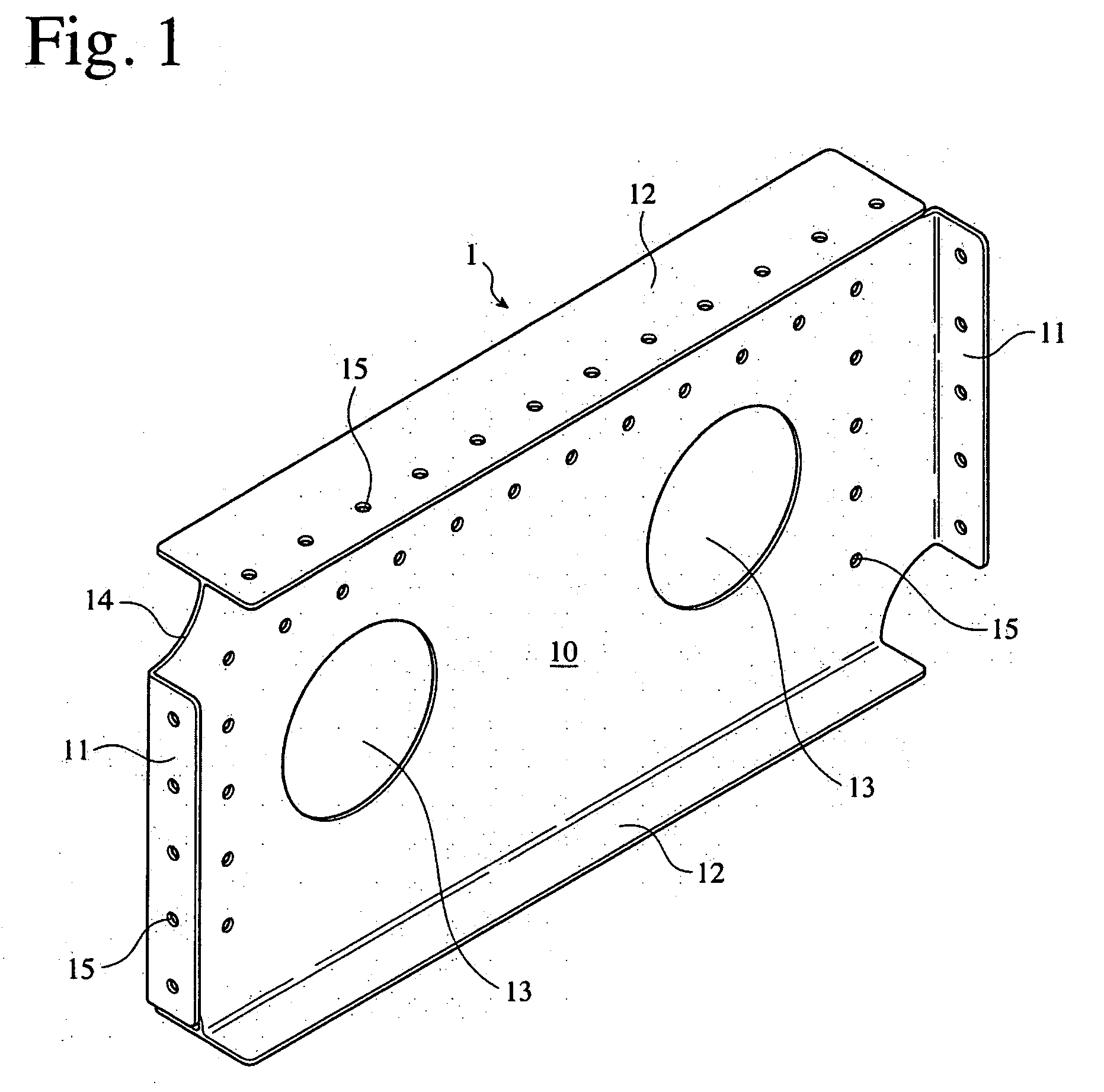
[0055]FIG. 1 shows one example of fiber-reinforced composites produced by the method of the present invention. This fiber-reinforced composite panel 1, which is produced by curing prepregs of reinforcing fibers impregnated with a matrix resin, comprises a rectangular, flat panel portion 10, flanges 11, 11 projecting from both transverse side edges of the flat panel portion 10 on one side, flanges 12, 12′ projecting from both longitudinal side edges of the flat panel portion 10 on both sides, circular holes 13, 13 provided in the flat panel portion 10 for weight reduction, and circular notches 14 provided at four corners of the flat panel portion 10. The flat panel portion 10, the flanges 11, 11 and the flange 12 of the fiber-reinforced composite panel 1 have holes 15 for connection to other members with connecting means such as rivets, etc. Taking for example the molding of the fiber-reinforced composite panel 1 shown in FIG. ...


PUM

PropertyMeasurementUnit
Temperatureaaaaaaaaaa
Thermal expansion coefficientaaaaaaaaaa

Abstract

A method for producing a fiber-reinforced composite member from prepregs of reinforcing fibers impregnated with a matrix resin, comprising placing the prepregs in a cavity of a molding die, cutting off excess margins of the prepregs along the edges of the cavity, and curing the matrix resin.

Description

FIELD OF THE INVENTION[0001]The present invention relates to a method for producing a fiber-reinforced composite member accurately and easily at lower cost.BACKGROUND OF THE INVENTION[0002]Cured prepreg moldings (fiber-reinforced composites) composed of carbon-fiber-reinforced plastics (CFRP), etc. are conventionally produced by curing prepregs with excess margins, and cutting off the excess margins from the resultant cured molding by a cutting tool such as an endmill, a rooter, etc., to secure high dimensional accuracy. However, the fiber-reinforced composites are hard to cut because of high strength and rigidity, resulting in rapid wear of cutting tools and thus short life of cutting tools. Also, fibers extend from the cut surface like fluff, and interlaminar peeling occurs on the cut surface by vibration during cutting, resulting in decrease in strength and fatigue failure. An endmill having fine diamond particles electrodeposited on cutting edges was proposed as that with improv...

Claims


Application Information

Patent Timeline
IPC IPC(8): C23C16/00
CPCB29C70/345B29K2105/246B29C2793/009B29C70/545
Inventor KONDO, JUNICHIKASAHARA, YUKI
Owner AMERICAN HONDA MOTOR COMPANY
Why Eureka
Try Eureka