Estimation of angular parameters of a signal at an antenna array

a technology of antenna array and angular parameters, which is applied in the direction of antennas, diversity/multi-antenna systems, transmission monitoring, etc., can solve the problems of high processing capacity, time-consuming and laborious, and the current smart antenna technique cannot be said to be superior to others for all considered transmission scenarios, etc., to achieve low complexity

Inactive Publication Date: 2007-12-13
TELEFON AB LM ERICSSON (PUBL)
View PDF7 Cites 34 Cited by
  • Summary
  • Abstract
  • Description
  • Claims
  • Application Information

AI Technical Summary

Problems solved by technology

When copies of the same signal arrive out of phase, they may subtract from one another, causing fading, an important but generally temporary attenuation of the signal.
Any one of the current smart antenna techniques cannot be said to be superior to others for all considered transmission scenarios.
In the prior art, procedures to allow for estimation of the AS are complex and require high processing capacities.
A main disadvantage of ML based methods is that a multidimensional numerical search is necessary.
Furthermore, the complexity of methods of a similar nature increases with a number of possible angular distributions to test, that is, such methods need to evaluate the AS for each of a Gaussian, Laplacian and Uniform distribution types.
Covariance matching estimators, although less complex than ML-based estimators, still require multidimensional searches, or at least multiple unidimensional searches, and as such are still quite complex.
Some form of these methods can be used without a priori knowledge of the angular distribution, at the cost of reduced estimation accuracy.
A problem of the above methods is with regards to numerical complexity.
Another problem is the fact that most of those methods require an a priori knowledge of the type of angular distribution.
For the beamforming method, there is also a problem related with the selection of angular ranges over which a search is being done.
A problem with this method is that a number of antenna elements must be greater than four, and obtained estimates are relatively precise only for low angular spreads, smaller than three degrees or so.

Method used


Image

  • Estimation of angular parameters of a signal at an antenna array
  • Estimation of angular parameters of a signal at an antenna array
  • Estimation of angular parameters of a signal at an antenna array

Examples


Embodiment Construction

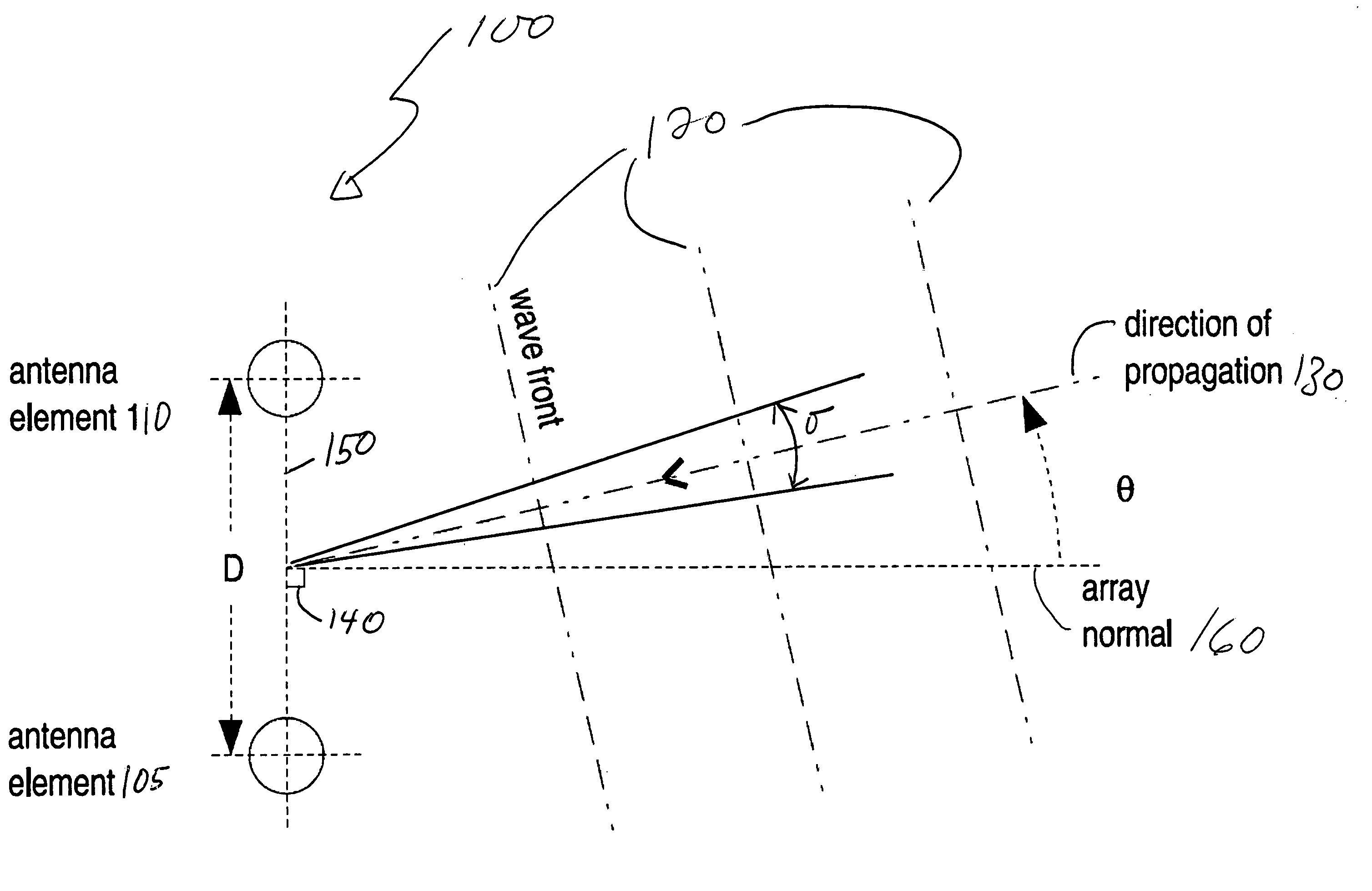
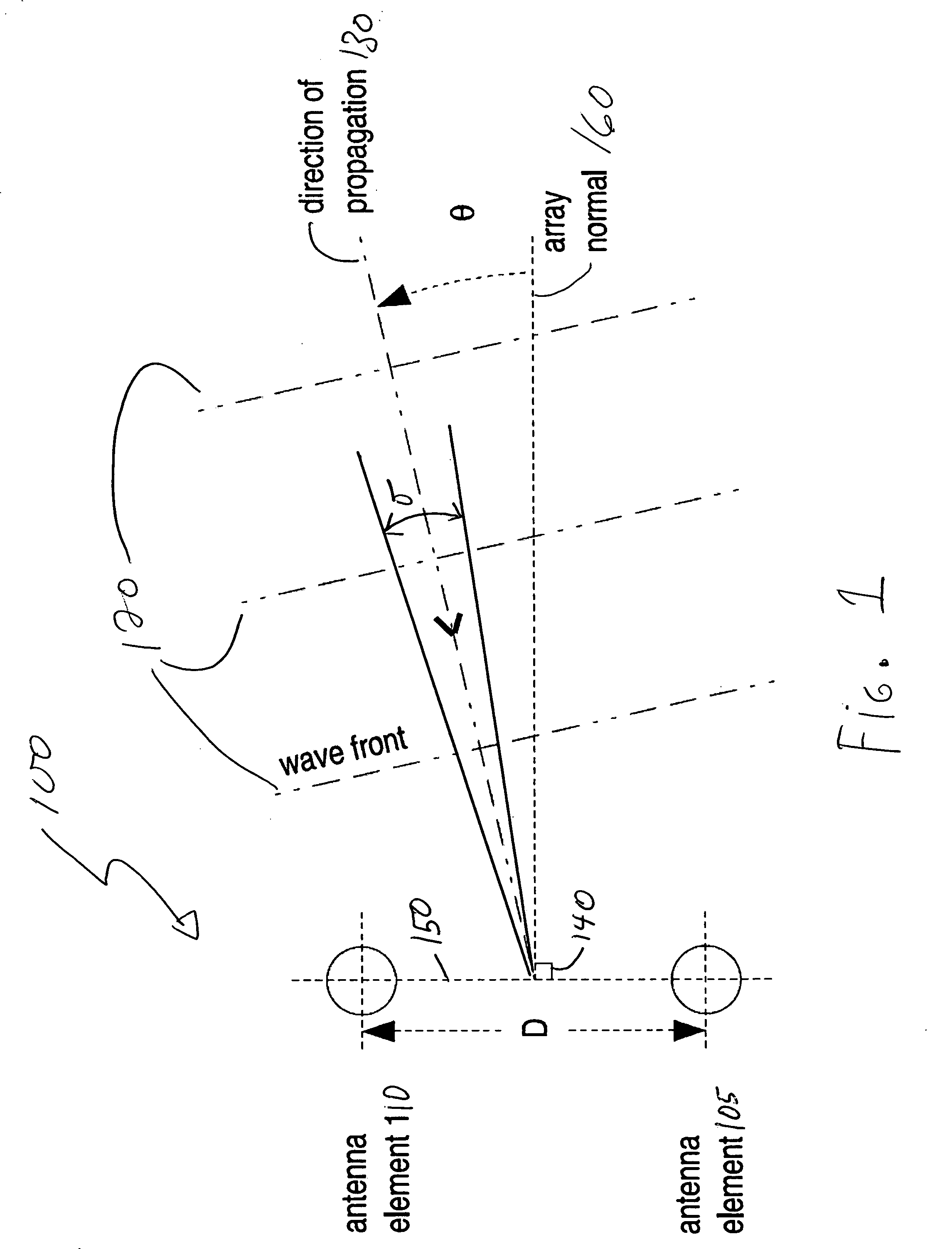
[0037]The innovative teachings of the present invention will be described with particular reference to various exemplary uses and aspects of the preferred embodiments. However, it should be understood that these embodiments provide only a few examples of the many advantageous uses of the innovative teachings of the invention. In general, statements made in the specification of the present application do not necessarily limit any of the various claimed aspects of the present invention. Moreover, some statements may apply to some inventive features but not to others. In the description of the figures, like numerals represent like elements of the invention.

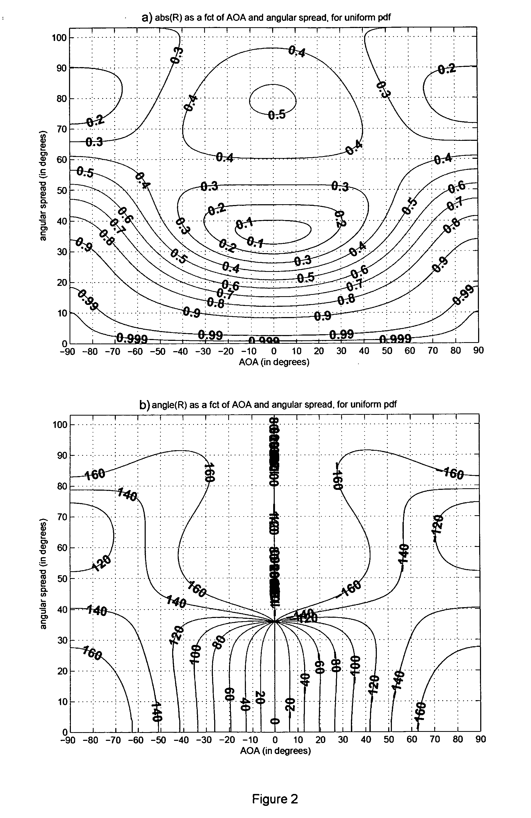
[0038]The present invention provides a method and an antenna array system taking advantage of mathematical models to provide knowledge of characteristics of radio channels to improve the use of antenna arrays. These mathematical models, for various types of radio channels, characterized by the manner in which the channels may dispers...


PUM


Abstract

A method and an antenna array system are provided for estimating parameters of radio signals impinging on antenna arrays, for estimating angular parameters, for estimating angular distribution types, and for selecting types of antenna array processing. Models of angular distribution types are used to populate look-up tables. Correlation magnitudes and correlation phases of signals impinging on antenna elements of antenna arrays are used as pointers to obtain values of parameters from the look up tables. The obtained values may be compared to some value ranges in order to select appropriate antenna array processing types. Where the angular distribution type is unknown, several values representing angular parameters may be obtained from look-up tables representing various models, and a variance of the angular parameter values for each model may be calculated. A low variance obtained from a look-up table is indicative that the model used to populate the look-up table is a good representation of the actual channel. In a network comprising a first node incorporating an antenna array and a second node, the first node may inform the second node about the type of signal distribution of the channel. This information is used by the second node to select the antenna processing type.

Description

BACKGROUND OF THE INVENTION [0001]1. Field of the invention[0002]The present invention relates to a method, and an antenna array system, for supporting estimation of angular parameters of signals received at an antenna array.[0003]2. Description of the Related Art[0004]An antenna system may comprise one or more antenna elements. In many cases, the antenna system is directional, in the sense that it provides good reception of a radio signal from a range of angles of arrival. Well-known wireless cellular systems oftentimes use three antennas, or preferably three pairs of antennas, within one cell site, each antenna or pair covering substantially 120 degrees of range, the three antennas or pairs altogether providing a full circular receiving range. A directional antenna generally provides more receiving gain than an unidirectional antenna, but this is true only for signals with an angle of arrival (AOA) that falls within its designed angular range. Signals that arrive outside of the de...

Claims


Application Information

Patent Timeline
Patent Type & Authority Applications(United States)
IPC IPC(8): H04B17/00H04M1/00
CPCH04B7/08H04B17/391H04B17/309
Inventor STEPHENNE, ALEX
Owner TELEFON AB LM ERICSSON (PUBL)
Why Eureka
Try Eureka