Method and apparatus for visual odometry

a visual odometer and visual odometer technology, applied in the direction of navigation instruments, instruments, cycle equipment, etc., can solve the problems of poor indoor performance, lack of versatility of most existing systems for autonomous navigation, and poor performance of gps-based navigation systems

Inactive Publication Date: 2007-12-13
SARNOFF CORP
View PDF12 Cites 43 Cited by
  • Summary
  • Abstract
  • Description
  • Claims
  • Application Information

AI Technical Summary

Problems solved by technology

However, most existing systems for autonomous navigation lack versatility in that they are typically environment-specific.
For example, GPS-based navigation systems work well in outdoor environments, but perform poorly indoors.
Navigation systems that rely on information from wheel encoders work w

Method used


Image

  • Method and apparatus for visual odometry
  • Method and apparatus for visual odometry
  • Method and apparatus for visual odometry

Examples


Embodiment Construction

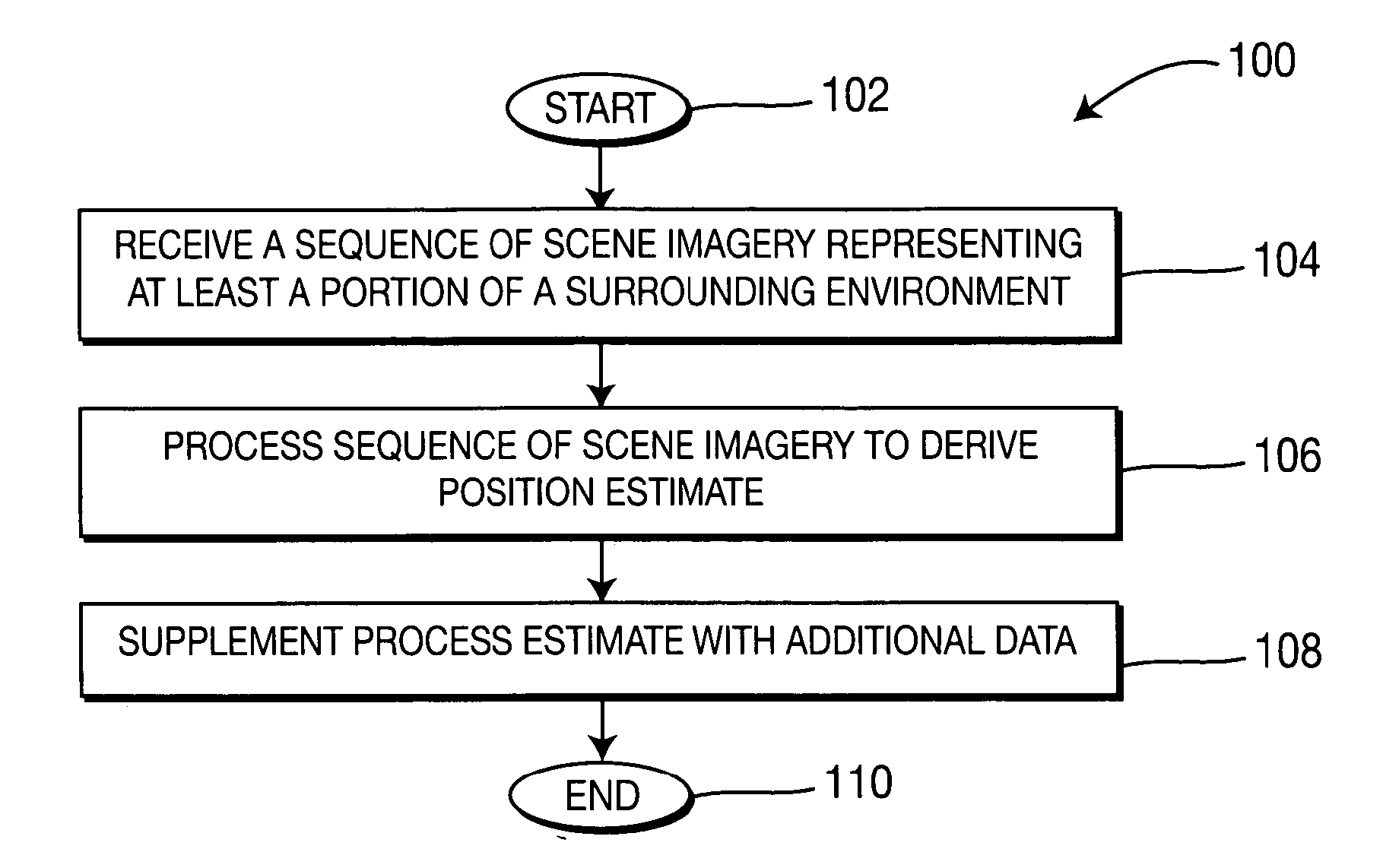
[0016] The present invention discloses a method and apparatus for visual odometry (e.g., for autonomous navigation of moving objects such as autonomous vehicles or robots). Unlike conventional autonomous navigation systems, in one embodiment, the present invention relies primarily video data to derive estimates of object position and movement. Thus, autonomous navigation in accordance with the present invention is substantially environment-independent. Environment-specific sensors, such as those conventionally used in autonomous navigation systems, serve mainly as optional means for obtaining data to supplement a video-based estimate.

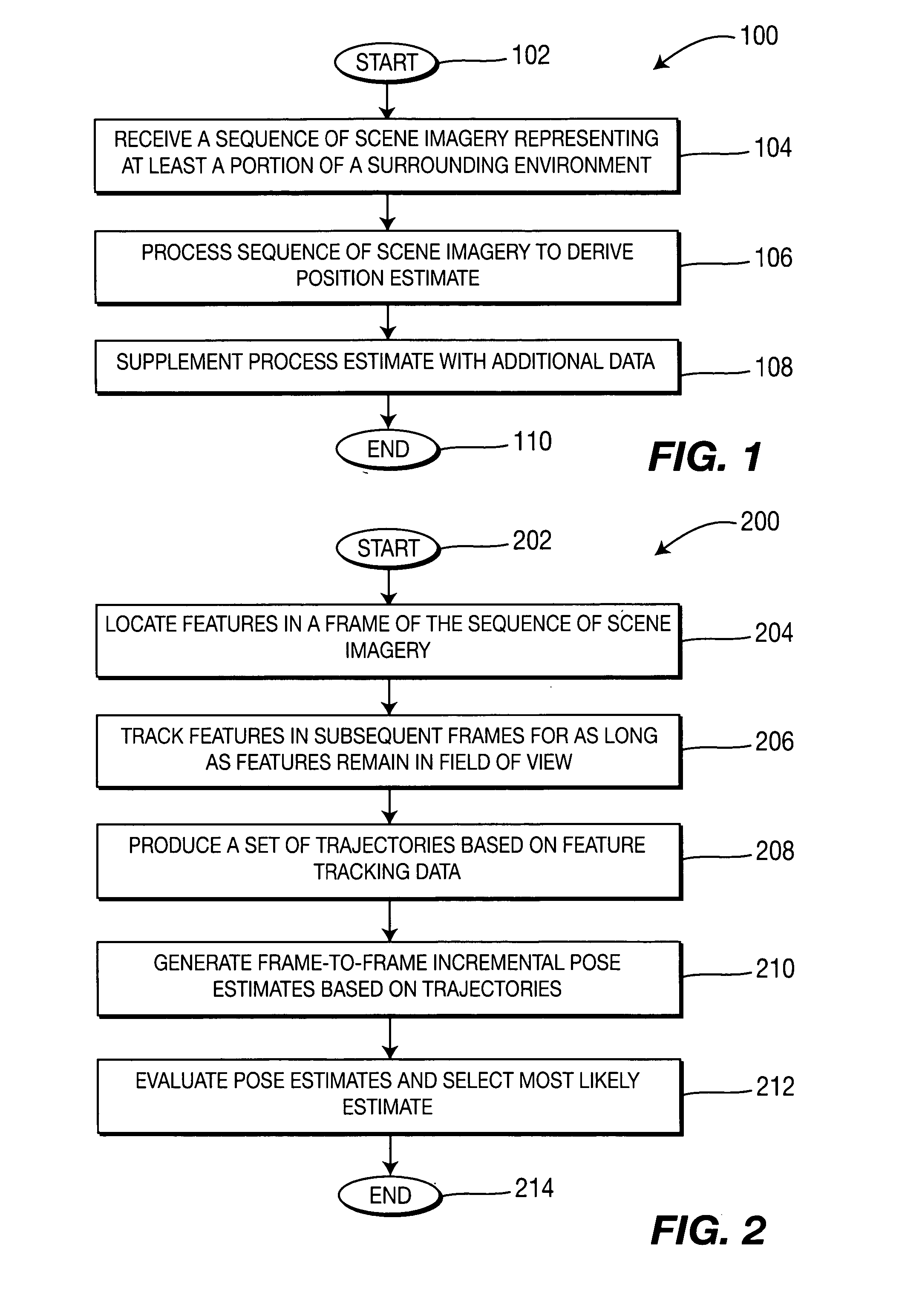
[0017]FIG. 1 is a flow diagram illustrating one embodiment of a method 100 for visual odometry, according to the present invention. The method 100 may be implemented in, for example, an object requiring navigation such as an autonomous (e.g., unmanned) vehicle or in a robot. The method 100 is initialized at step 102 and proceeds to step 104, where the ...


PUM


Abstract

A method and apparatus for visual odometry (e.g., for navigating a surrounding environment) is disclosed. In one embodiment a sequence of scene imagery is received (e.g., from a video camera or a stereo head) that represents at least a portion of the surrounding environment. The sequence of scene imagery is processed (e.g., in accordance with video processing techniques) to derive an estimate of a pose relative to the surrounding environment. This estimate may be further supplemented with data from other sensors, such as a global positioning system or inertial or mechanical sensors.

Description

CROSS-REFERENCE TO RELATED APPLICATIONS [0001] This application claims benefit of U.S. provisional patent application Ser. No. 60 / 581,867, filed Jun. 22, 2004, which is herein incorporated by reference in its entirety.REFERENCE TO GOVERNMENT FUNDING [0002] The invention was made with Government support under grant number MDA972-01-9-0016 awarded by the Defense Advanced Research Projects Agency (DARPA). The Government has certain rights in this invention.BACKGROUND OF THE INVENTION [0003] The utility of computer vision systems in a variety of applications is recognized. For example, autonomous navigation systems (e.g., for vehicles and robots) rely heavily on such systems for obstacle detection and navigation in surrounding environments. Such systems enable the navigation and / or surveillance of difficult or dangerous terrain without putting human operators at risk. [0004] However, most existing systems for autonomous navigation lack versatility in that they are typically environment-...

Claims


Application Information

Patent Timeline
IPC IPC(8): G01C21/00
CPCG01C21/005G06T7/0042G01C21/165G06T7/73G01C21/1656
Inventor BERGEN, JAMES RUSSELLNARODITSKY, OLEGNISTER, DAVID
Owner SARNOFF CORP
Why Eureka
Try Eureka