Accelerator Pedal Module And Full Load Indicator For Said Accelerator Pedal Module

a technology of accelerator pedal module and full load indicator, which is applied in the direction of mechanical control devices, instruments, process and machine control, etc., can solve the problems of increasing the cost and weight of the pedal, and increasing the difficulty of pedal movement, so as to improve the resistance, save costs and weight, and be easy to mount the module

Inactive Publication Date: 2007-12-20
DAIMLER AG
View PDF5 Cites 19 Cited by
  • Summary
  • Abstract
  • Description
  • Claims
  • Application Information

AI Technical Summary

Benefits of technology

[0006] If the full load indicator is embodied as a belt with a curved contour, a reliable indication of the full load, which can be perceived in a haptic fashion, for a corresponding position of the pedal can take place for the driver in a very simple fashion.
[0007] An abruptly increased resistance can be opposed to the pedal movement if, toward its free end, the full load indicator has, on its concave inner surface, a step toward a center point of curvature. Without interaction with the full load indicator, the pedal can execute pedal travel from an idling position to a position with a high power demand of a drive engine / motor until a corresponding interaction element, preferably a driver of the restoring device, can impact against the step of the full load indicator. If the pedal is moved further in the same direction of increasing power demand, the region of the full load indicator beyond the step makes movement of the pedal more difficult. The driver senses an abruptly increasing resistance which he perceives, for example, as a jump in the operating force of the pedal and which indicates to him that he is opening the throttle completely.
[0008] If the full load indicator is integrated together with the restoring device into a housing, a compact, easy-to-mount module can be obtained. The mounting of a separate kickdown catch can be dispensed with. This saves costs and weight.
[0009] If the restoring device bears with a pivotably movable driver against the full load indicator, at least near to the full load position, a very simple and reliable device with which a further pedal movement is opposed with resistance can be provided by latching the driver to the full load indicator. At the same time, the restoring device ensures that, as the loading by the driver's foot decreases, the pedal can be released from contact with the full load indicator.
[0010] The full load indicator is preferably adapted in its contour to a movement curve of the driver. As a result, existing installation space in the housing of the accelerator pedal module can be utilized without increasing the size of the accelerator pedal module.
[0011] A particularly cost-effective and weight-saving configuration is possible if the full load indicator is formed from plastic. The full load indicator is particularly preferably embodied as a spring plate. This permits particularly simple geometry and adaptation both to the housing contour and to the pivoting movement of the driver. Optionally, the full load indicator can be embodied as a roll with a compression spring or as a so-called claw with a spring.

Problems solved by technology

Such full load indicators are generally complex and a considerable cost factor.
If the pedal is moved further in the same direction of increasing power demand, the region of the full load indicator beyond the step makes movement of the pedal more difficult.
This saves costs and weight.

Method used


Image

  • Accelerator Pedal Module And Full Load Indicator For Said Accelerator Pedal Module
  • Accelerator Pedal Module And Full Load Indicator For Said Accelerator Pedal Module
  • Accelerator Pedal Module And Full Load Indicator For Said Accelerator Pedal Module

Examples


Embodiment Construction

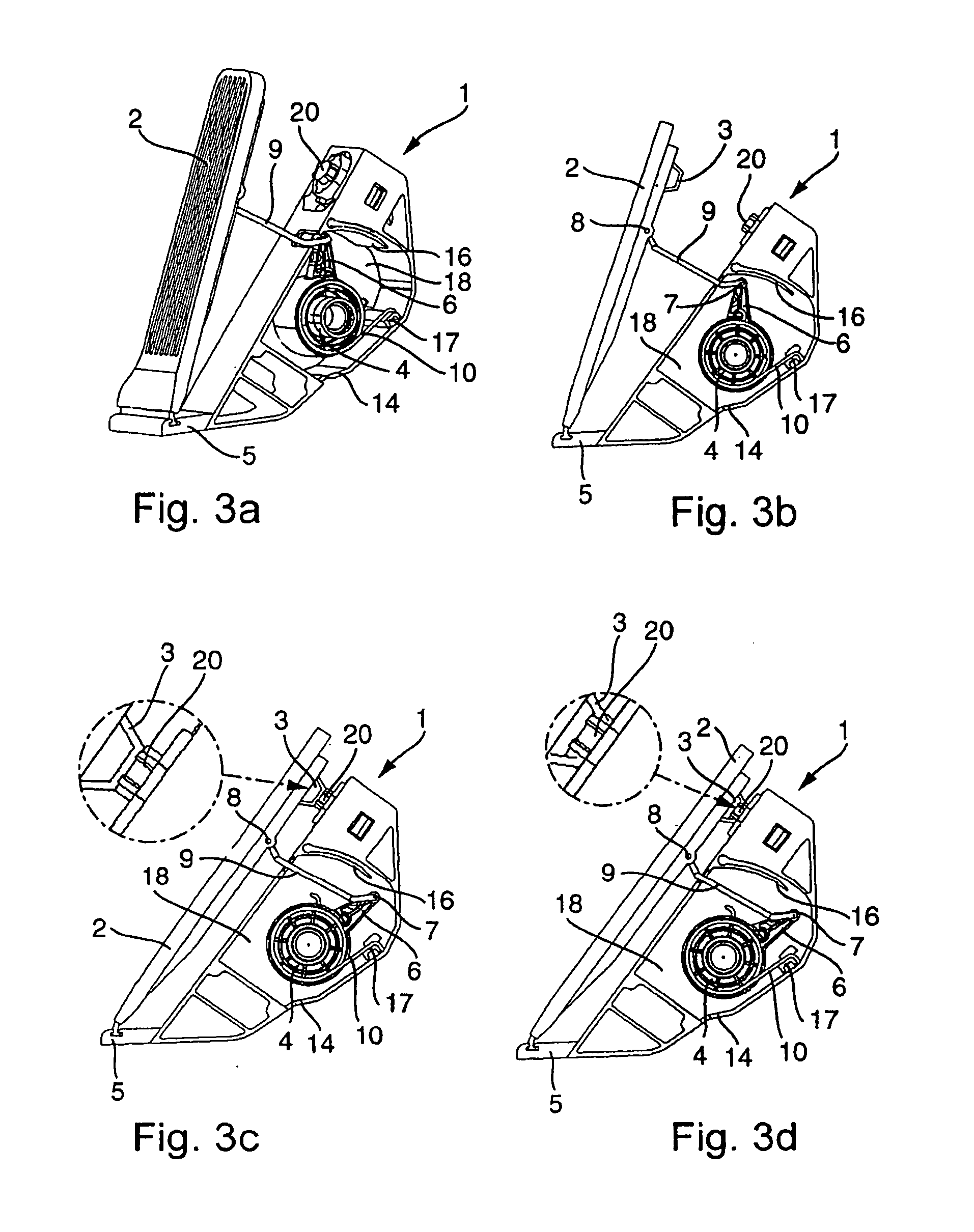
[0018] In the figures, basically identical parts are provided with the same reference symbols.

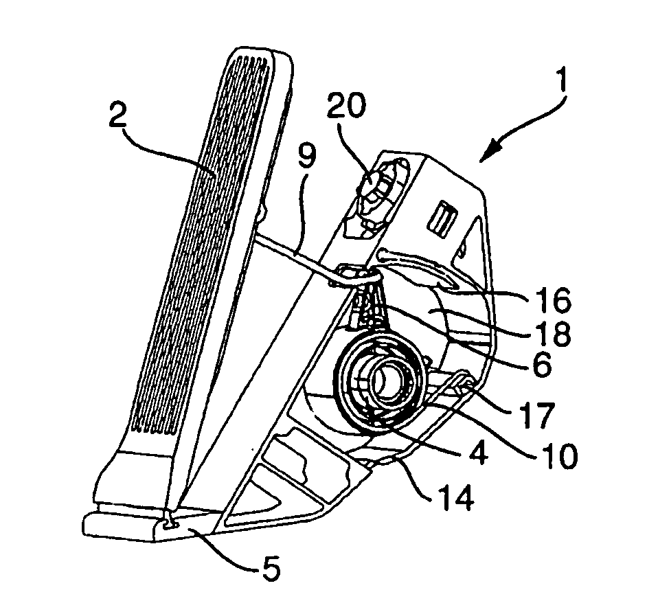
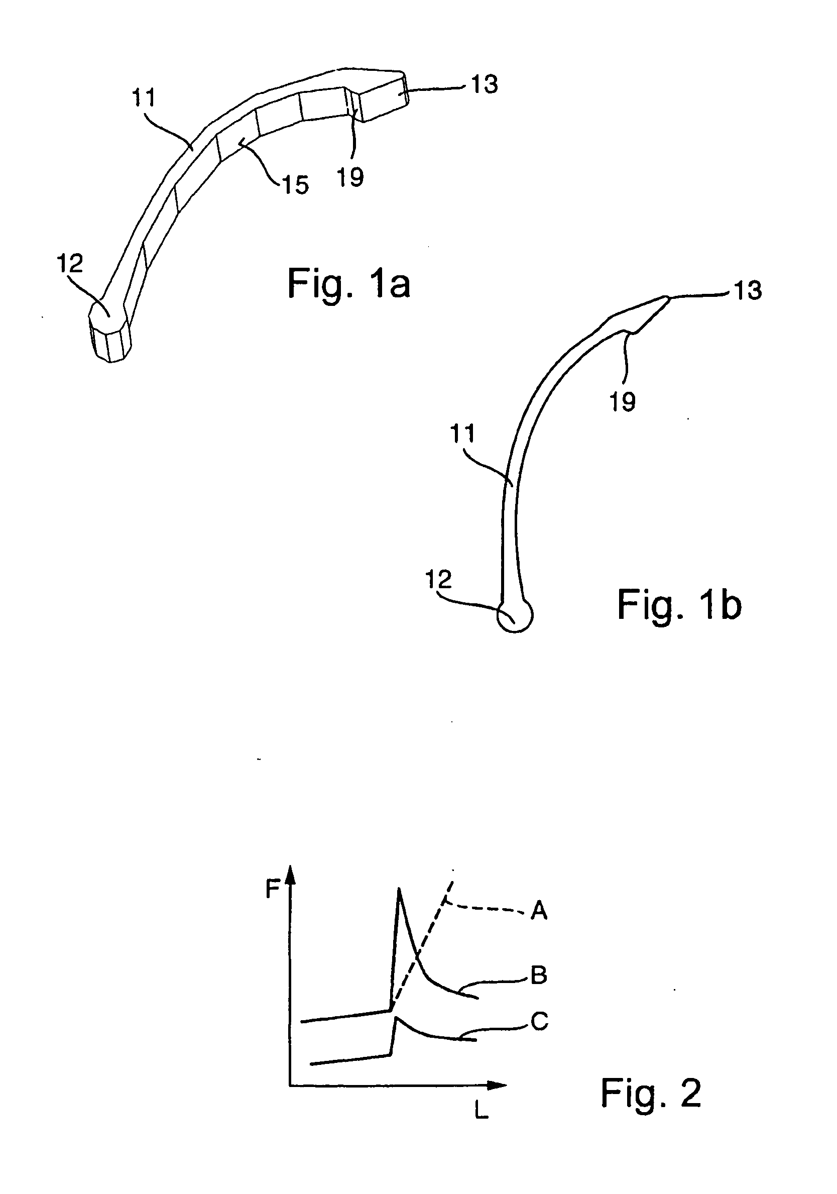
[0019] A preferred accelerator pedal module full load indicator 11 is illustrated in FIGS. 1a and 1b. The oblique plan view in FIG. 1a shows a belt-shaped base body with a curvature along its longitudinal extent, which protrudes with a first end 12, for supporting the accelerator pedal module full load indicator 11, in an accelerator pedal module, and a second end 13 which, in the installed state, protrudes freely into a housing (not illustrated) of the accelerator pedal module. The broadside of the base body has a concavely curved inner surface 15 and a correspondingly convexly curved outer surface. The full load indicator 11 is preferably embodied as a spring element. Starting from the first end 12, the curvature of the base body of the full load indicator 11 increases toward the free end 13.

[0020]FIG. 1b shows a longitudinal section through the preferred full load indicator 11. Near to...


PUM


Abstract

The invention relates to an accelerator pedal module having a pedal (2) and a restoring device (4) for the pedal (2) as well as a full load indicator (20, 11). In the full load position of the pedal (2), the restoring device (4) can be latched to the full load indicator (11). Furthermore, the invention relates to an accelerator pedal module full load indicator.

Description

BACKGROUND AND SUMMARY OF THE INVENTION [0001] The present invention relates to an accelerator pedal module and an accelerator pedal module full load indicator. [0002] It is known to equip accelerator pedal modules with a full load indicator. Such a full load indicator, for example a so-called kickdown catch, is necessary for reliable functioning of an automatic transmission in combination with a cruise controller and / or a speed limiting device. For example, starting from a specific pedal travel, an electrical signal is generated for the kickdown catch. That signal is conveyed to the driver as a haptically perceptible, abruptly increasing resistance as soon as this pedal travel occurs. It is known, for example, to arrange a magnetic kickdown catch with a restoring spring and a magnetic arrangement as an additional component of an accelerator pedal module underneath the pedal. Such full load indicators are generally complex and a considerable cost factor. Such a kickdown catch is kno...

Claims


Application Information

Patent Timeline
Patent Type & Authority Applications(United States)
IPC IPC(8): G05G1/14G05G1/38G05G1/30
CPCG05G1/38Y10T74/20534G05G5/03
Inventor LA, TAN-PHATPAPENHAGEN, DIETER
Owner DAIMLER AG
Why Eureka
Try Eureka