Hrv/erv with improved air flow balancing and method of operating the same

Active Publication Date: 2014-04-17
SALERNO JOSEPH
View PDF10 Cites 13 Cited by
  • Summary
  • Abstract
  • Description
  • Claims
  • Application Information

AI Technical Summary

Benefits of technology

[0011]What is desired is a simple and easy to use HRV and/or ERV unit that can reliably maintain a balanced airflow between the fresh air and the exhaust air without requiring manual measurement, visual inspection of gauges or pitot tubes, manual adjustments of dampers or the like, and most preferably does not require the services of a skilled and expensive technician for each and every installation. Such a device should provide a balanced airflow under all conditions regardless of site specific aerodynamic issues and should be able to maintain such a balanced airflow in light of changed conditions either by reasons of a change to the site-specific ventilation ducting configuration, which can change the aerodyna

Problems solved by technology

Although the fans can be calibrated in a factory setting to a predetermined flow rate, site-specific installation parameters can affect the aerodynamic head for the inflow and outflow lines and thus volumetric performance of the fans.
Unfortunately, this airflow balancing adjustment requires considerable time from the technician and there is no easy way for a building occupant to be able to tell if it is been done correctly, or indeed, if at all.
In other cases changes to the airflow system or in air pressure can affect the balancing and so what might have been balanced at one point can get out of balance.
Further there is a tendency for the fan characteristics to change over time, due to changes in the lubrication and wear on the mechanical parts, or even an accidental c

Method used


Image

  • Hrv/erv with improved air flow balancing and method of operating the same
  • Hrv/erv with improved air flow balancing and method of operating the same
  • Hrv/erv with improved air flow balancing and method of operating the same

Examples


Example

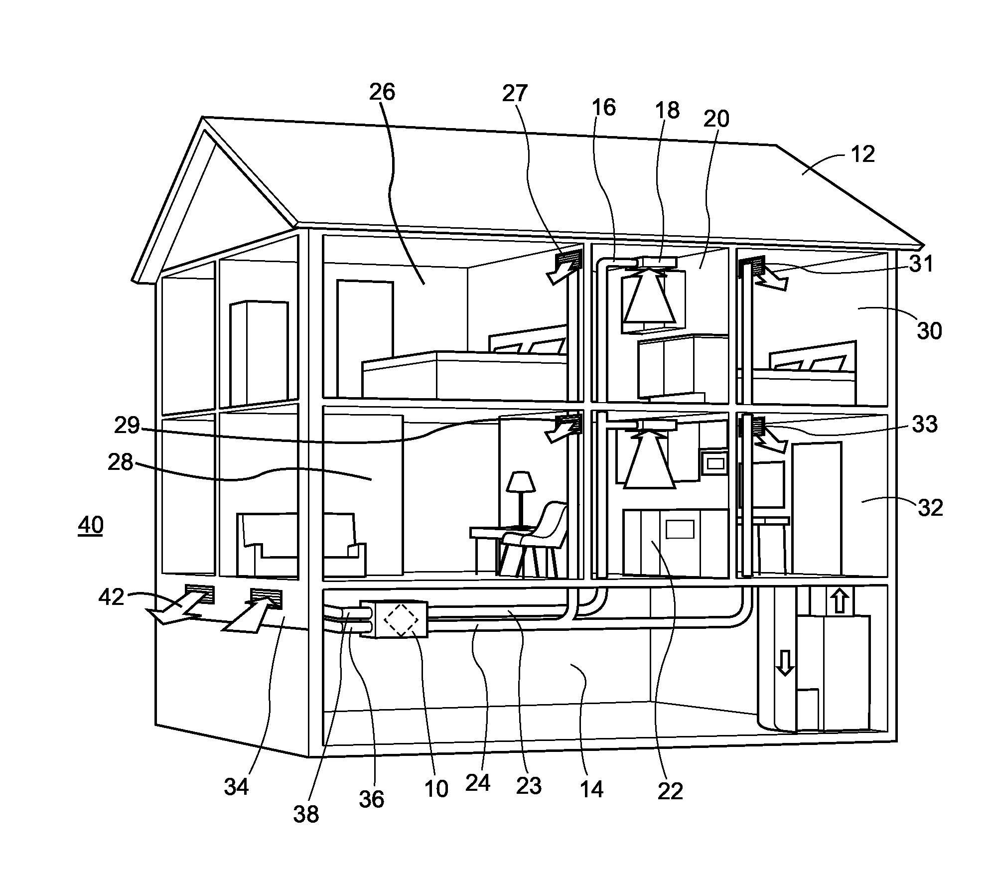
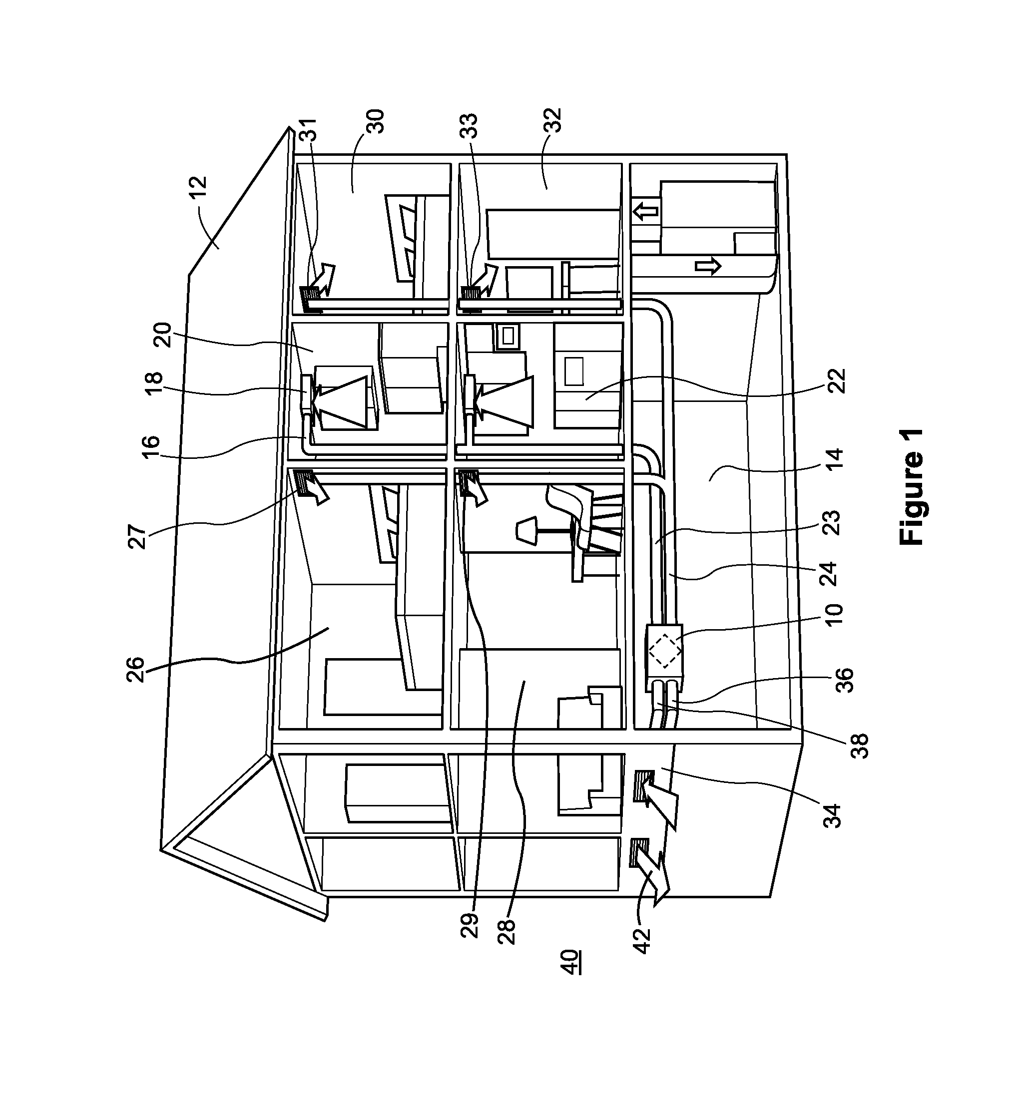
[0037]FIG. 1 shows a heat energy recovery ventilation unit 10 installed in the building 12. In the present specification the term building means any structure with living quarters that requires fresh air turn over. Thus the term building comprehends single or multiple family dwellings such houses, duplexes, apartments in high rise buildings, condominium units, row houses and any other enclosed living or occupation space that requires an inflow of fresh air and an exhaust of stale air to meet the needs of living breathing occupants.

[0038]The unit 10 may be installed in a basement 14, for example, and includes ducting leading up to and away from the unit 10. The unit 10 is sized and shaped to be installed in either a vertical orientation or a horizontal orientation. Good results have been achieved with an overall size of about 27¾ inches in width, about 21 inches in depth and about 9 inches in height, and having a total weight of between 50 and 60 pounds, most preferably about 55 poun...


PUM


Abstract

A heat and energy recovery ventilation unit for a building, having an inside and an outside. The unit including a main body having a fresh air inlet and an indoor air outlet on one side and a fresh air outlet and an indoor air inlet on the other side and having an air to air heat exchanger within the main body and connected to each of said inlets and outlets to define respective air flow passageways for each of said indoor air and said fresh air, the heat exchanger permitting heat and energy exchange between said indoor air and said fresh air. Also included is a first variable speed blower and a second variable speed blower and at least one electronic air flow sensor to measure at least one of the air flows the air flow sensor producing at least one electronic signal related to the sensed air flow. Also included is a controller for receiving the data signal, the controller using the data signal to control at least one of the variable speed blowers to provide a balanced fresh air inflow and indoor air outflow through the ventilation unit. A method of operating the unit is also disclosed.

Description

FIELD OF THE INVENTION[0001]This invention relates generally to the field of ventilation and more particularly to ventilation of residential and commercial living spaces. Fresh air is needed for the comfort and health of building occupants. Most particularly this invention relates to air to air heat exchangers of the type which may be used to transfer heat and energy from an exhaust air stream being expelled from a building into a fresh air stream being drawn into the building to replace the stale air being exhausted from the building.BACKGROUND OF THE INVENTION[0002]Ventilation of building's occupied by humans is required. Such ventilation is required to provide fresh oxygen to the occupants of the building and to remove stale air with high concentrations of CO2 for health and comfort reasons. Modern construction and building codes have imposed certain requirements on building ventilation systems. In particular modern construction focuses on heavily insulated and air tight building...

Claims


Application Information

Patent Timeline
IPC IPC(8): F24F11/04
CPCF24F11/04F24F12/006F24F2110/30F24F11/77Y02B30/56Y02B30/70F24F11/74
Inventor SALERNO, JOSEPH
Owner SALERNO JOSEPH
Why Eureka
Try Eureka