Pressure Regulating Valve

a pressure regulating valve and valve body technology, applied in the direction of fluid pressure control, process and machine control, instruments, etc., can solve the problems of low durability of rubber seals that are typically used as seals, large fluctuations in the secondary pressure of the pressure regulating valve, and insufficient damping

Inactive Publication Date: 2007-12-20
TOYOTA JIDOSHA KK
View PDF10 Cites 14 Cited by
  • Summary
  • Abstract
  • Description
  • Claims
  • Application Information

AI Technical Summary

Benefits of technology

[0018] By providing communicating means, the space and the reference pressure chamber are made to communicate, and it is possible to regulate the pressure value of the space at the ...

Problems solved by technology

However, there is the problem that rubber seals that are typically used as seals have low durability.
Further, when hard resin seal material of high durability is used, it is not possible to obtain a sufficient damping acti...

Method used


Image

  • Pressure Regulating Valve
  • Pressure Regulating Valve
  • Pressure Regulating Valve

Examples


first embodiment

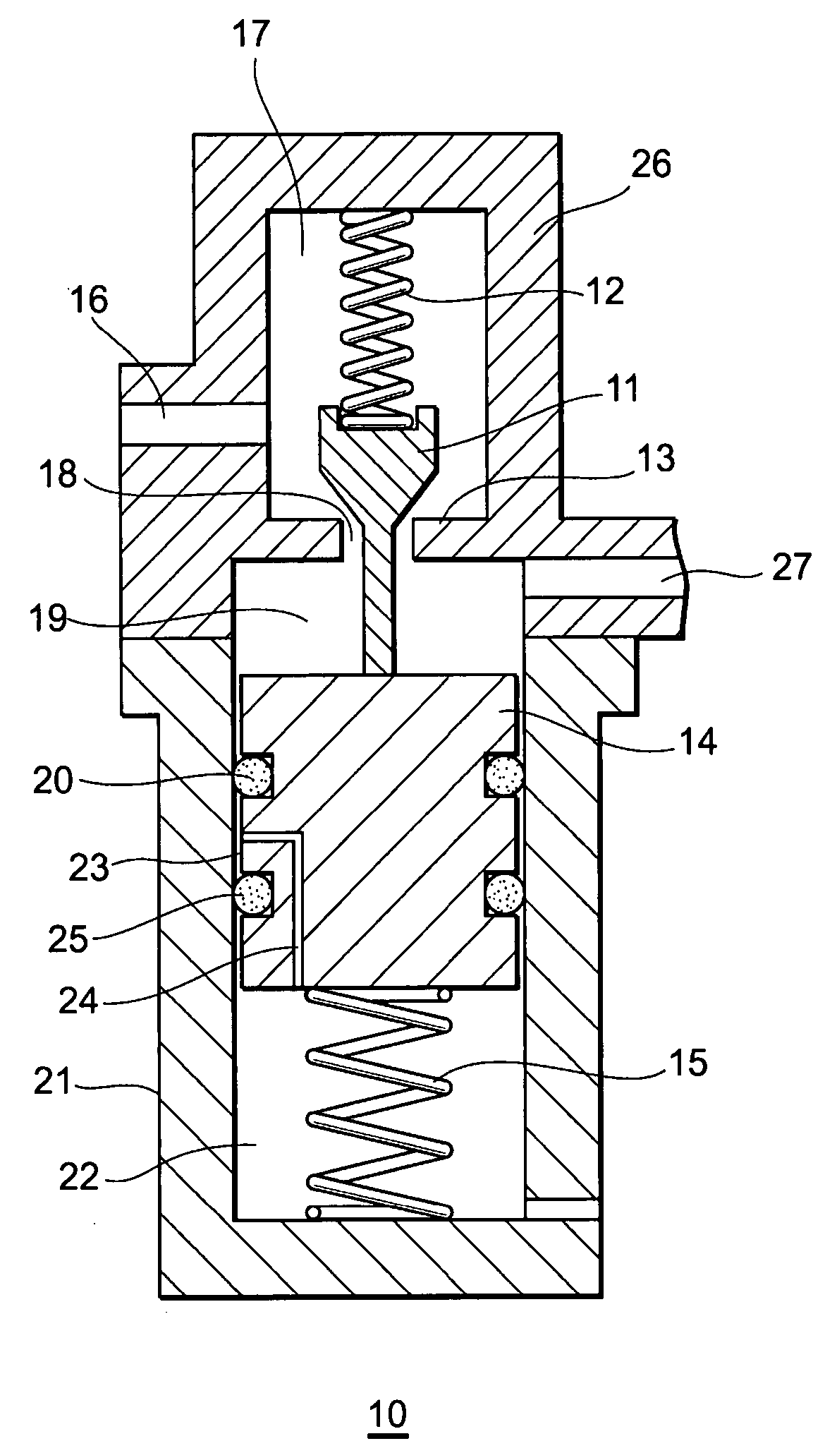
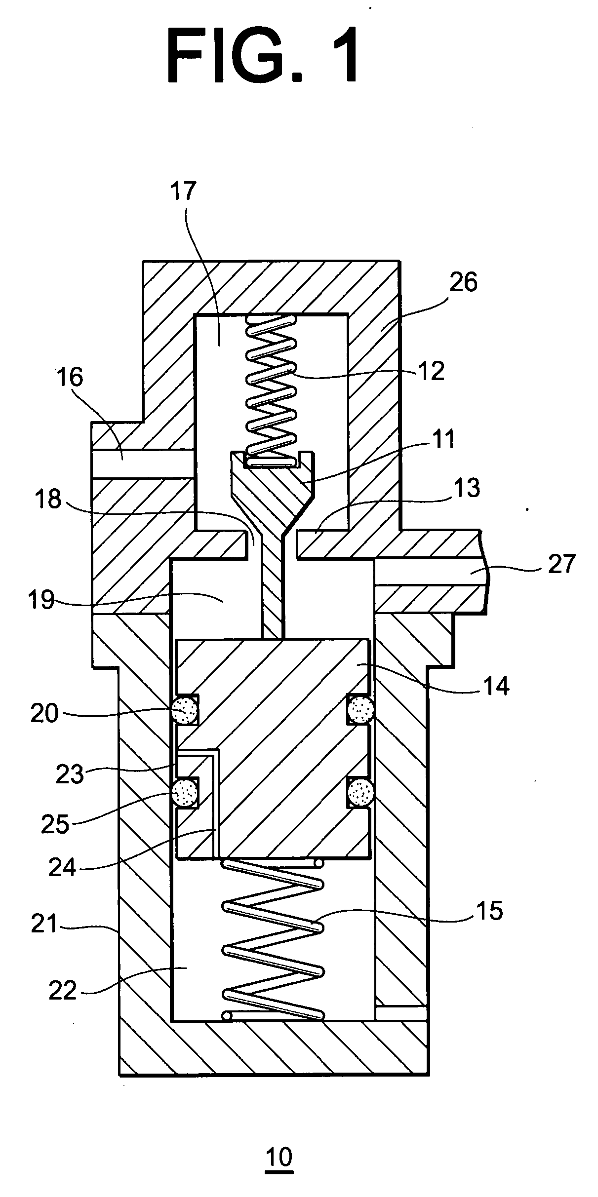
[0039] The following is a description with reference to FIG. 1 of a first embodiment of a pressure regulating valve 10 of the present invention.

[0040] In FIG. 1, numeral 11 indicates a poppet valve, numeral 12 indicates a spring constituting urging means for the poppet valve, numeral 13 indicates a seat, numeral 14 indicates a piston, numeral 15 indicates a spring constituting piston urging means, numeral 16 indicates a high-pressure gas path (inlet-path), numeral 17 indicates a primary chamber of the pressure regulating valve, numeral 18 indicates a path, numeral 19 indicates a secondary chamber of the pressure regulating valve, numeral 20 indicates a ring-type seal, numeral 21 indicates a cylinder (case), numeral 22 indicates a reference pressure chamber (reference pressure chamber), numeral 23 indicates a space, numeral 24 indicates a path, numeral 25 indicates a damper, numeral 26 indicates a pressure regulating valve case, and numeral 27 indicates a low pressure gas path (outl...

second embodiment

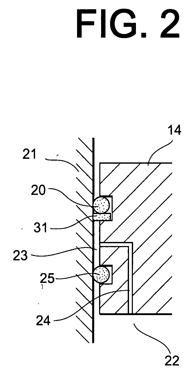
[0049]FIG. 2 shows an outline of a second embodiment of the present invention. In FIG. 2, portions corresponding to portions of FIG. 1 are given the same numerals and are not described.

[0050] In this embodiment, an annular back-up ring 31 is overlaid on the polymer material ring-type seal 20. The reliability of the seal is increased as a result of providing the back-up ring 31.

third embodiment

[0051]FIG. 3 shows a third embodiment of the present invention. FIG. 3(A) shows an outline of an example of a further configuration for the polymer material ring-type damper 25 and FIG. 3(B) shows an example of a partial cut-away view from above taken along A-A′ of FIG. 3(A). In FIG. 4, portions corresponding to portions of FIG. 1 are given the same numerals and are not described.

[0052] In this example, minute undulations 32 are formed at a contact surface for an inner wall surface of the cylinder 21 of the damper 25 in place of the path 24 of the piston 14 or alternatively, the surface is roughened so that gas can communicate between the space 23 and the reference pressure chamber 22.


PUM


Abstract

In order to achieve seal durability and bring about a damping action for a piston-type pressure regulating valve, a pressure regulating valve (10) of the present invention is characterized by a valve moving member (11, 14) moving in such a manner as to cause communication or block communication between a primary chamber (17) and a secondary chamber (19) within a case (21, 26), wherein a plurality of central members (20, 25) are arranged between the case and the valve moving member and the plurality of central members are taken to be different materials. It is then possible to bring about both a damping action and seal durability using the central members by providing central members of different materials.

Description

TECHNICAL FIELD [0001] The present invention relates to a pressure regulating valve for regulating fluid pressure. BACKGROUND ART [0002] Pressure regulating valves such as disclosed in, for example, Japanese Utility Model Laid-open Publication No. Hei. 1-178285, exist as pressure regulating valves for reducing pressure of gases. Such pressure-reducing valves are configured from a pressure regulating spring, a piston moving within a cylinder, a valve element, and a return spring etc. Between the piston and cylinder is then sealed using a U-shaped seal. DISCLOSURE OF THE INVENTION [0003] However, there is the problem that rubber seals that are typically used as seals have low durability. Further, when hard resin seal material of high durability is used, it is not possible to obtain a sufficient damping action (attenuating action) with respect to movement (vibration or oscillation, over shoot) of the valve using the rubber seal material and fluctuations in the secondary pressure of the...

Claims


Application Information

Patent Timeline
IPC IPC(8): F16K17/00
CPCF16K31/1221G05D16/10F16K31/1223G05D16/107Y10T137/7722Y10T137/7793Y10T137/7825Y10T137/7826
Inventor ISHITOYA, TSUKUOKOBAYASHI, NOBUOOGAMI, NOBUYUKIYAMASHITA, AKIRA
Owner TOYOTA JIDOSHA KK
Why Eureka
Try Eureka