Structural support and tracking system

a tracking system and support technology, applied in the direction of solar heat collector controllers, mounting/supporting heat collectors, moving/orienting solar heat collectors, etc., can solve the problems of placing very large torques and moments on these gear boxes, and achieve the effect of light weigh

Inactive Publication Date: 2011-08-25
ETERNEGY
View PDF2 Cites 21 Cited by
  • Summary
  • Abstract
  • Description
  • Claims
  • Application Information

AI Technical Summary

Benefits of technology

[0018]The present invention is directed to a structural support and tracking system which provides substantially accurate displacement / tracking, also upon displaced at substantially small increments. The manipulating construction is light weight and nevertheless provides rigidity and durability also at the event of strong wind. Even more so, the system may be tilted with respect to the horizon at significant degrees, optionally exceeding 90°.
[0043]the utility platform is fitted to the support post via a coupling link rendering it freedom to tilt at an angle of at least 90° with respect to the X-Y plane.
[0045]the support post comprises a dampening mechanism facilitating to retain the utility platform substantially stable at a respective tilts position thereof.
[0056]It is appreciated that the system is substantially light weight, though is suited for bearing heavy loads of the utility platform and for example wind. On the other hand the system may rapidly assume a stowed position in case of strong wind, whereby the utility platform is directed so as to cause a minimal disturbance to the wind.

Problems solved by technology

Wind loads on large area collectors place very large torques and moments on these gear boxes.

Method used


Image

  • Structural support and tracking system
  • Structural support and tracking system
  • Structural support and tracking system

Examples


Embodiment Construction

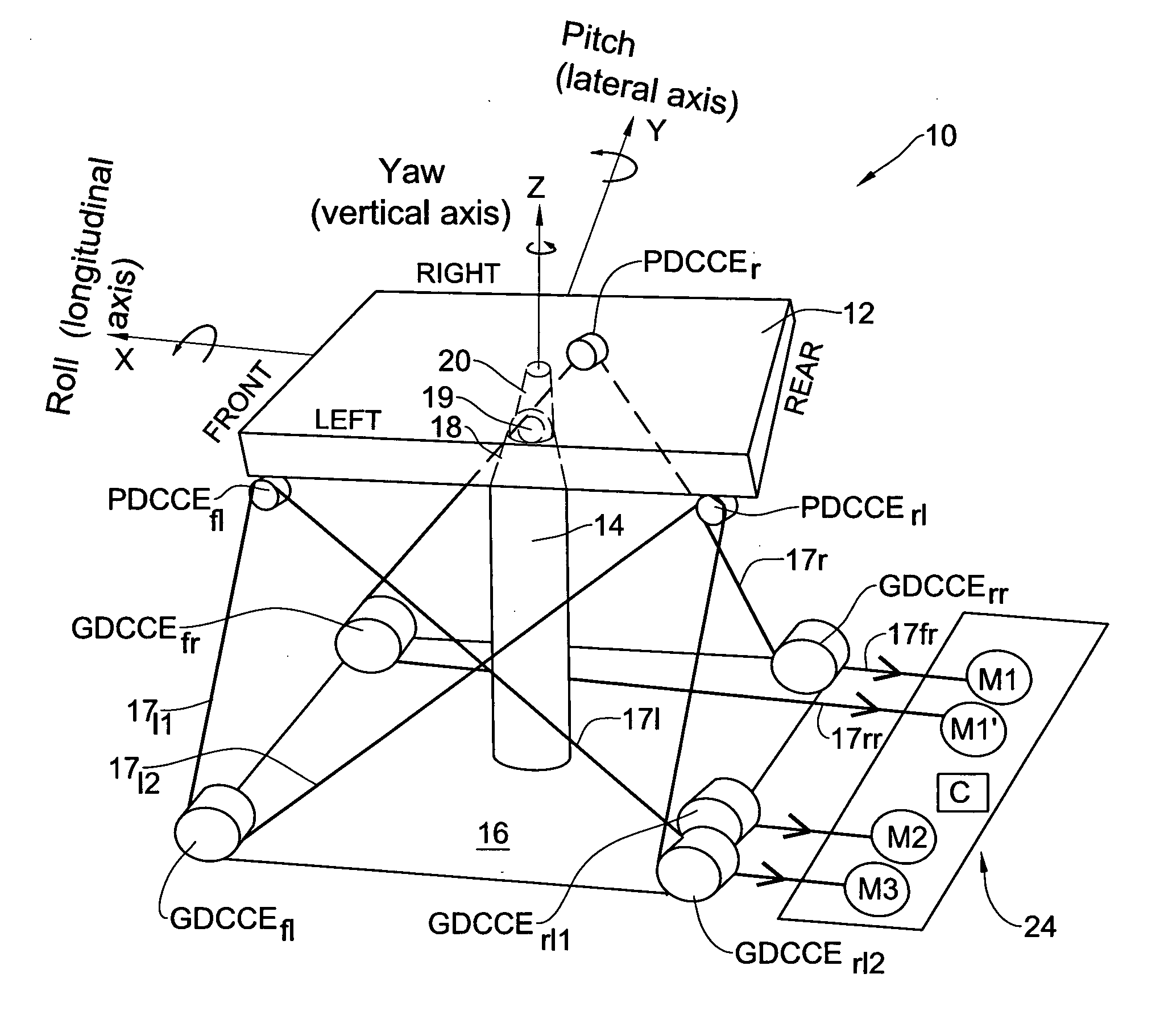
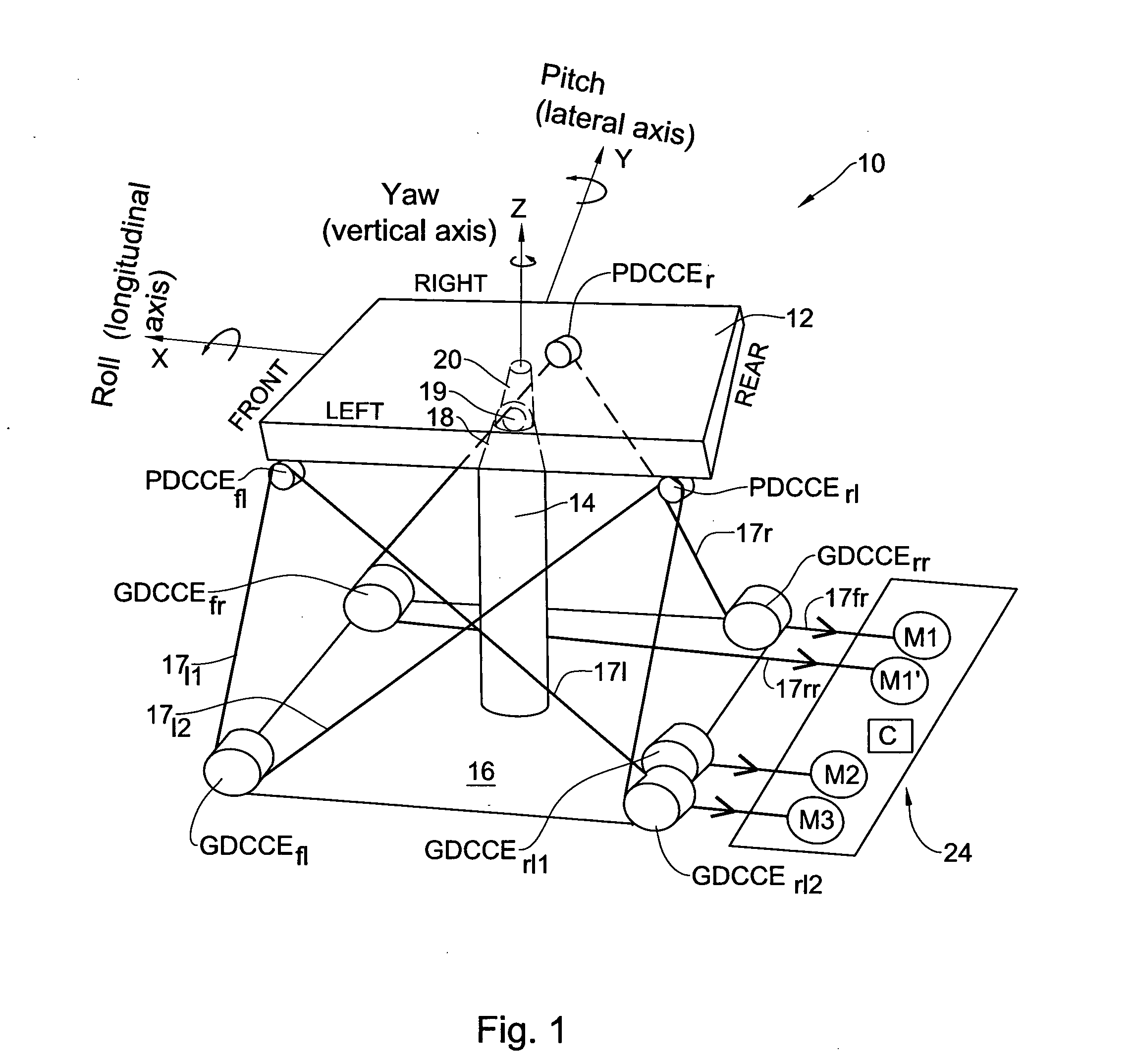
[0075]Turning first to FIG. 1 of the drawings there is schematically illustrated a structural support / tracking system in accordance with the present invention generally designated 10, comprising a utility platform 12 which in the present case is a flat, rigid, rectangle plate tiltably supported over a support post 14 rigidly fixed to the ground surface 16, via a first joint 18, a support link 19 and a second free joint 20 (e.g. a ball and socket joint with extension link, universal joint, Cardan joint, etc.). The link and joints enable the utility platform 12 to tilt at 90° or more.

[0076]The utility platform 12 is defined over a longitudinal axis X and a lateral axis Y. The utility platform 12 further defines a front side and a rear side extending along the longitudinal X-X axis. A manipulating system generally designated 24 comprises three motors M1, M2 and M3 and a controller assembly C, to be discussed hereinafter in further detail. The longitudinal axis X-X is the axis about whi...


PUM


Abstract

A structural support and tracking system comprising a utility platform defining an X-Y plane and supported over a central support post defining a longitudinal axis Z being normal to the plane X-Y. The utility platform comprises at least three platform cord connection elements, at least three left ground cord connection elements associated with two left platform cord connection elements, and at least one right ground cord connection element associated with at least one right platform cord connection element (PCCE). A tension cord system wherein a cord extends from each platform cord connection element towards at least one corresponding ground cord connection elements, and a manipulating system for tilting the utility platform by tension adjustment of the cords.

Description

FIELD OF THE INVENTION[0001]This invention relates to support system carrying a utility platform, wherein the platform is spatially manipulable. The support system is useful for example, as a tracking system or as a support structure for various construction purposes, etc.BACKGROUND OF THE INVENTION[0002]Tracking systems for flat and concentrating panels are used to focus / direct solar energy and other forms of radiation onto a receiver which collects the radiation or signal for use. The tracker must keep the collecting surface pointing at the sun or energy source so that maximum energy will be absorbed by the receiver. For that purpose it is required that a tracking system be capable of accurate incremental angular displacement.[0003]The prior art contains a number of examples of methods for azimuth and elevation tracking of energy concentrating antennas and solar collectors. Most conventional heliostat and dish trackers use pedestal mounted gear box drives to provide azimuth and el...

Claims


Application Information

Patent Timeline
Patent Type & Authority Applications(United States)
IPC IPC(8): G05B13/00F16M11/18
CPCF24J2/38F24J2/5431F24J2002/5286Y02E10/47F24J2002/5472H01Q1/1242H01Q3/08F24J2002/5458F24S30/48F24S2025/017F24S50/20F24S2030/133F24S2030/137
Inventor DROR, EYAL
Owner ETERNEGY
Why Eureka
Try Eureka