Laser Welding Method

a laser welding and keyhole technology, applied in welding equipment, metal-working equipment, manufacturing tools, etc., can solve the problems of difficult to stably maintain a keyhole, easy blowhole and cracking, and weld defects such as porosity

Inactive Publication Date: 2007-12-20
NAT INST FOR MATERIALS SCI +1
View PDF6 Cites 8 Cited by
  • Summary
  • Abstract
  • Description
  • Claims
  • Application Information

AI Technical Summary

Benefits of technology

[0009] It is, therefore, an object of the present invention to provide a new laser welding method, which is proposed by the inventors, of measuring light emission strength of a plasma signal, analyzing a variation frequency of the signal so as to be capable of optimizing a laser output variation condition more simply and securely.
[0010] In order to solve the above problem, a first aspect of the present invention provides a laser welding method of varying a waveform and a frequency of a laser output in a controlled manner so as to prevent occurrence of weld defects, which comprises detecting a time change in light emission strength of plasma or plume generated from a laser welded portion, and setting a laser output variation condition so that the time change in the light emission strength responds to the variation in the laser output.
[0011] A second aspect of the present invention provides a laser welding method of varying a waveform and a frequency of a laser output in a controlled manner so as to prevent occurrence of weld defects, which comprises detecting a time change in light emission strength of plasma or plume generated from a laser welded portion, analyzing the frequency characteristics of the light emission to obtain an amplitude of a frequency component which is the same or near a variation frequency of the laser output, and setting a laser output variation condition so that the amplitude of the frequency component becomes maximum.
[0012] A third aspect of the present invention provides a laser welding method of varying a waveform and a frequency of a laser output in a controlled manner so as to prevent occurrence of weld defects, which comprises detecting the time change in the light emission strength of the plasma or plume generated from the laser welded portion, setting an arbitrary threshold value to the time change in the light emission strength of the plasma or plume, and setting the laser output variation condition so that a sum of time at which the light emission strength becomes the threshold value or less becomes minimum.
[0014] According to the present invention, the light emission strength of the plasma or plume generated from the laser emitted position is measured so that the laser output variation condition is optimized, but in this invention, an attention is paid particularly to a relationship between the laser output variation frequency and the light emission strength. The laser output variation frequency and the light emission strength are suitably analyzed and processed, so that the optimum laser output variation frequency can be found more simply and quickly.

Problems solved by technology

In the deep penetration welding, however, as the welding becomes deeper, it is more difficult to stably maintain a keyhole formed by a laser emitted portion, and thus weld defects such as porosity, blowhole and crack easily occur accordingly.

Method used


Image

  • Laser Welding Method
  • Laser Welding Method
  • Laser Welding Method

Examples


examples

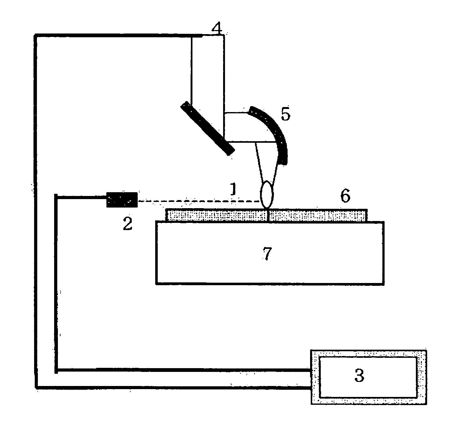
[0047] Steel SM490A for general weld structure was used so that partial penetration welding was carried out on a bead-on-plate. At the time of welding, in order to prevent occurrence of the weld defects, as shown in FIG. 7, a laser output was varied by a triangular wave with peak output of 20 kW and base output of 8 kW. Rise time at which the base output varies into the peak output was 10 ms which is constant, and the frequency was changed within the range of 10 Hz to 98 Hz. The device having the constitution shown in FIG. 3 was used, and the light emission strength of the plasma at the time of welding was measured by Si photodiode 2 (Si—Pd) with a sensitivity wavelength range of 190 to 1100 μm at a sampling frequency of 50 kHz. Si—PD was installed on a horizontal extension of the same level as an object to be welded (6). A laser (4) beam was converged on the surface of the object to be welded (6) by a parabolic mirror (5) with a focal distance of 500 mm. A test piece with width of ...


PUM

PropertyMeasurementUnit
lengthaaaaaaaaaa
lengthaaaaaaaaaa
natural frequencyaaaaaaaaaa

Abstract

In a laser welding method of varying a waveform and a frequency of a laser output in a controlled manner so as to prevent occurrence of weld defects, a time change in light emission strength of a plasma or plume generated from a laser welded portion is detected, a laser output variation condition is set so that the time change in the light emission strength is in response to the variation in the laser output during laser welding. In a laser welding method of varying the waveform and frequency of a laser output suitably so as to prevent the occurrence of the weld defects, a new laser welding method can optimize a laser output variation condition more simply and securely.

Description

TECHNICAL FIELD [0001] The present invention relates to a laser welding method. More specifically, the present invention relates to a new laser welding method which can optimize a laser output variation condition more simply and securely in a laser welding method of suitably varying waveform and frequency of a laser output so as to prevent occurrence of weld defects such as porosity, blowhole and crack. BACKGROUND ART [0002] In recent years, since enlargement of output in laser oscillators has significantly proceeded, this is expected to be applied to deep penetration welding and high-speed welding. In the deep penetration welding, however, as the welding becomes deeper, it is more difficult to stably maintain a keyhole formed by a laser emitted portion, and thus weld defects such as porosity, blowhole and crack easily occur accordingly. For this reason, in order to apply laser techniques to wide-range process of materials including structural materials, the techniques that securely...

Claims


Application Information

Patent Timeline
Patent Type & Authority Applications(United States)
IPC IPC(8): B23K26/00B23K26/03
CPCB23K26/03B23K26/032B23K31/125B23K26/20B23K26/06B23K26/21
Inventor TSUKAMOTO, SUSUMUKAWAGUCHI, ISAOARAKANE, GOROHONDA, HIROSHI
Owner NAT INST FOR MATERIALS SCI
Why Eureka
Try Eureka