
Drian Valve Assembly

a technology of valve assembly and valve body, which is applied in the direction of valve housing, valve operating means/release devices, machines/engines, etc., can solve the problems of drain plug unscrewing, leakage, and process often messy job

Inactive Publication Date: 2007-12-20
RICHCO
View PDF27 Cites 7 Cited by
  • Summary
  • Abstract
  • Description
  • Claims
  • Application Information

AI Technical Summary

Benefits of technology

[0020] Another object is to provide a drain valve assembly which is easy and inexpensive to fabricate and simple and efficient to use.

Problems solved by technology

Draining the crankcase of a small engine is frequently done by a home owner and not by a trained mechanic, and that process is often a messy job.
The unscrewing of the drain plug is frequently associated with a spill of the oil or other liquid.
Oftentimes, the drain will begin to leak before the plug is fully opened, and turning it one way or the other will cause the draining to cease or create a steadier uncontrolled flow.
Obviously, uncontrolled spills are not only messy, but are adverse to the environment and sometimes dangerous, as the fluid tends to soak into whatever surface it drains to, is often difficult to clear or clean and is some times combustible.
All of these systems are believed to require relatively difficult designs or not suitable or versatile enough for most types of simple drain application or involve risk of leaks or handling of messy parts or dangerous materials to accomplish the fluid draining job.

Method used


Image

  • Drian Valve Assembly
  • Drian Valve Assembly
  • Drian Valve Assembly

Examples


Embodiment Construction

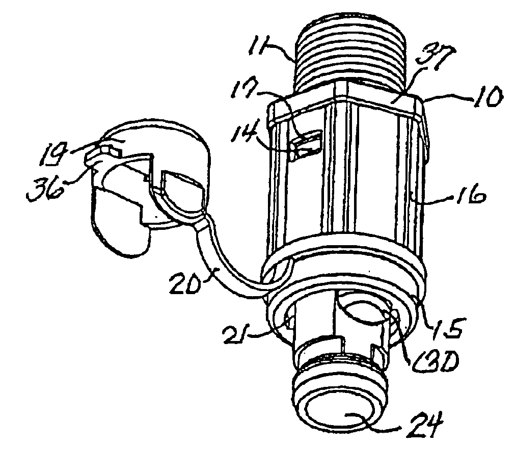
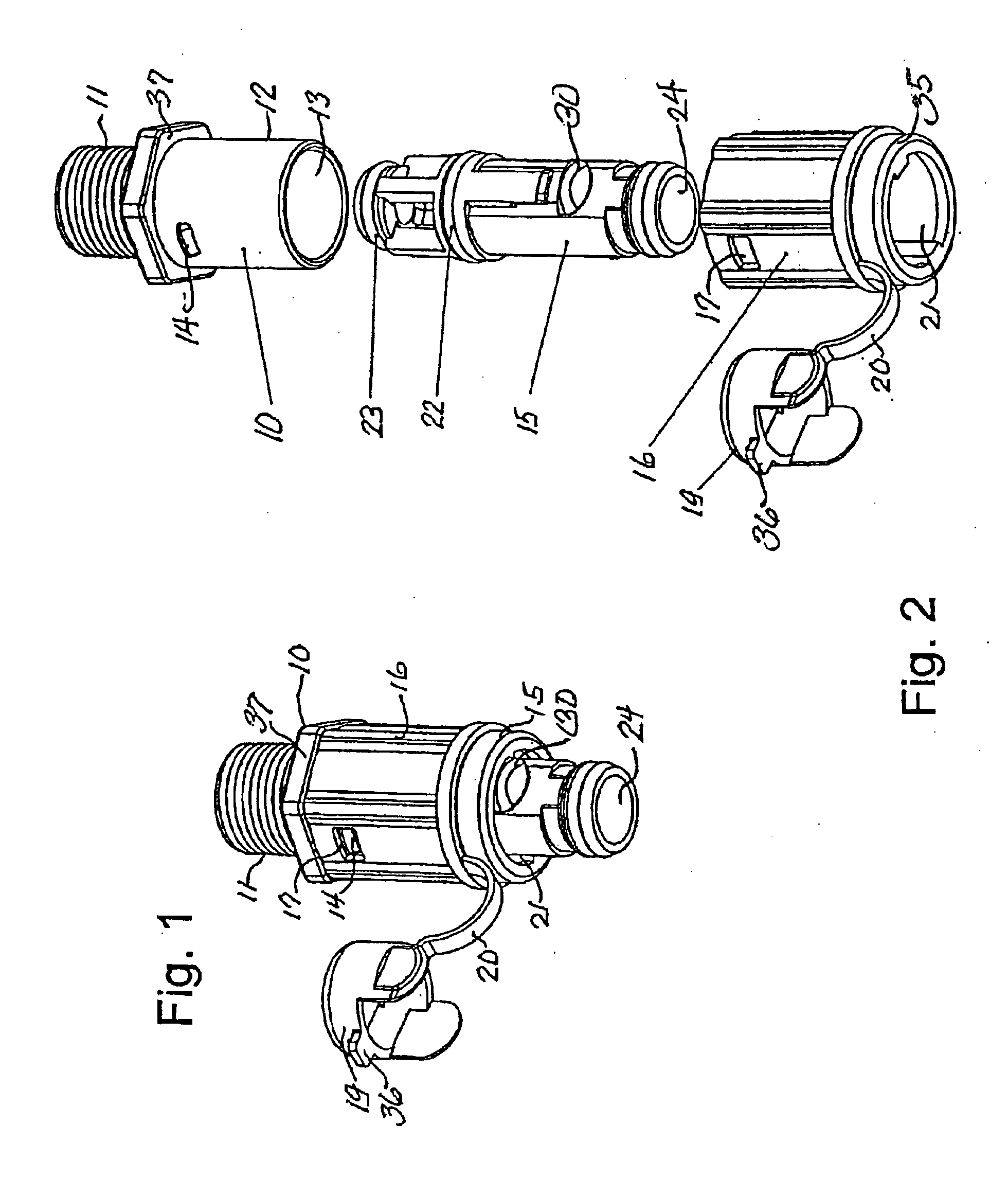
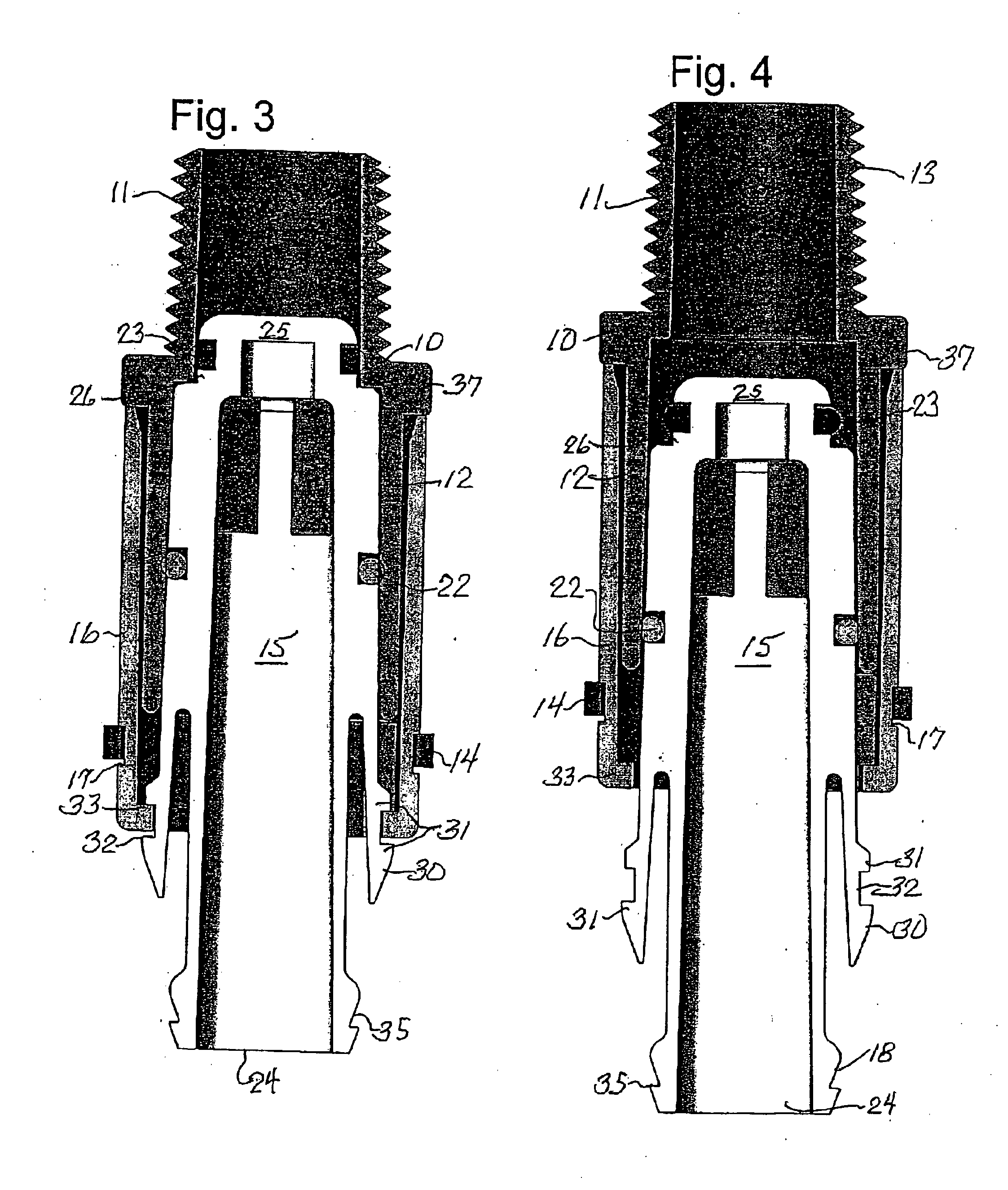
[0027] With reference to the accompanying drawings, a typical drain valve assembly embodying the present invention comprises a stem 10, which may have a threaded end 11 adapted for insertion in the crankcase of an engine (not shown). The other end of the stem 10 remote from the threaded end 11 comprises a sleeve 12, and this entire stem has an axial passage 13 which permits the flow of fluid therethrough. This sleeve 12 has on opposed exterior sides thereof at least two ribs 14 extending therefrom. One end of a sealing barrel 15 is positioned in the sleeve 12, and the other end of the sealing barrel 15 extends through an outside housing 16. This outside housing 16 has an interior diameter sized to overlay the sleeve 12 of the stem 10, and has apertures 17 which engage the ribs 14 of the sleeve to hold the housing 16 and stem together overlaying the sealing barrel 15. At the end 18 of the barrel 15 remote from the stem 15 a safety end cap 19 tethered to the housing by a strap 20 is a...


PUM


Abstract

A drain valve assembly having a stem which can be inserted into a crankcase or other fluid reservoir, wherein the stem is connected to a housing which encloses a sealing barrel movably secured and sealed in the connected stem and housing, and wherein the sealing barrel can be manipulated in a single direction from the exterior of the assembly to open or close a fluid passage through the assembly. An end cap may also be provided tethered to the housing for sealing off the fluid passage. Selected movement of the sealing barrel in the connected stem and housing may also be used to control the volume and flow of fluid through the fluid passage.

Description

[0001] Priority in this application is based upon a Provisional Patent Application filed Oct. 26, 2004, identified as U.S. Ser. No. 60 / 622,465.[0002] This invention related to a drain valve assembly for withdrawing fluid from a reservoir and is particularly concerned with draining fluid from a crankcase or the like, particularly in small engines like those found in lawn and garden tractors, small gasoline appliances, and the like. BACKGROUND AND SUMMARY OF THE INVENTION [0003] Draining the crankcase of a small engine is frequently done by a home owner and not by a trained mechanic, and that process is often a messy job. Conventionally, this job is done by unscrewing a draincock or plug at the lowest point of the crankcase or fluid reservoir. The unscrewing of the drain plug is frequently associated with a spill of the oil or other liquid. Oftentimes, the drain will begin to leak before the plug is fully opened, and turning it one way or the other will cause the draining to cease or ...

Claims


Application Information

Patent Timeline
IPC IPC(8): F16K31/44
CPCF01M11/0408F16K41/04F16K27/02F16K21/00
Inventor JANG, SAM
Owner RICHCO
Learn More