
Imaging Device, Product Package, and Semiconductor Integrated Circuit

a semiconductor integrated circuit and imaging device technology, applied in the field of image pickup apparatus, can solve the problems of ineffective technique for correcting the camera shaking of static images, limited apparatus size, and inability to perform static image correction in principl

Active Publication Date: 2007-12-20
PANASONIC CORP
View PDF6 Cites 40 Cited by
  • Summary
  • Abstract
  • Description
  • Claims
  • Application Information

AI Technical Summary

Benefits of technology

[0007] The technique using the electronic camera shaking correction method does not require any optical driving section. Therefore, it is possible to reduce the size of the apparatus. However, it has been considered that this technique is not effective for correcting the camera shaking of a static image. This is because this technique performs only a correction between a plurality of frames and it is impossible in principle to perform the camera shaking correction for a static image consisting of a single frame.
[0059] According to the image pickup apparatus of the present invention, it is possible to obtain the locus information required for the correction of the shaking motion. The locus information may be output to a device external to the image pickup apparatus (e.g., a computer). With this arrangement, it is possible to perform the correction of the shaking motion, which requires a large amount of processing, in the device external to the image pickup apparatus (e.g., a computer).

Problems solved by technology

For this reason, a reduction in the size of the apparatus is limited.
However, it has been considered that this technique is not effective for correcting the camera shaking of a static image.
This is because this technique performs only a correction between a plurality of frames and it is impossible in principle to perform the camera shaking correction for a static image consisting of a single frame.

Method used


Image

  • Imaging Device, Product Package, and Semiconductor Integrated Circuit
  • Imaging Device, Product Package, and Semiconductor Integrated Circuit
  • Imaging Device, Product Package, and Semiconductor Integrated Circuit

Examples


Embodiment Construction

[0188] Hereinafter, embodiments of the present invention will be described below with reference to the drawings.

[0189] 1. Image Pickup Apparatus

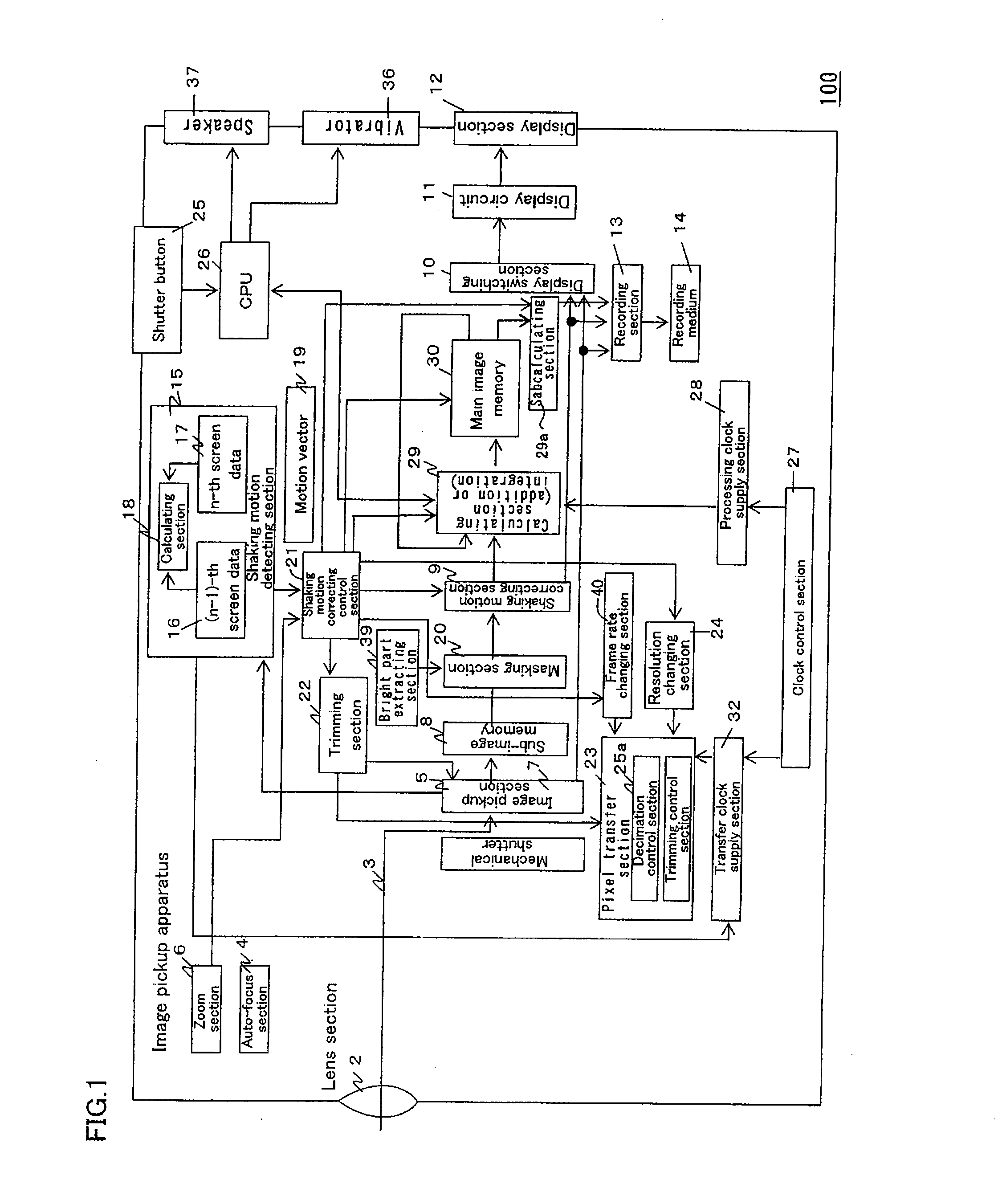
[0190]FIG. 1 shows an image pickup apparatus 100 according to an embodiment of the present invention.

[0191] The image pickup apparatus 100 takes a static image (i.e. a still image) during a predetermined exposure period. The image pickup apparatus 100 includes a lens section 2 for receiving light incident on the image pickup apparatus 100 from the outside of the image pickup apparatus 100; an auto-focusing section 4 for automatically adjusting a focus of the light 3; a zoom section 6 for setting a zoom ratio of the lens section 2; and an image pickup section 5. An optical image is formed on the image pickup section 5. The image pickup section 5 outputs data indicating the formed optical image. The image pickup section 5 is, for example, a CCD or a MOS type imaging device. The focus of the light 3 from the lens section 2 is automatically a...


PUM


Abstract

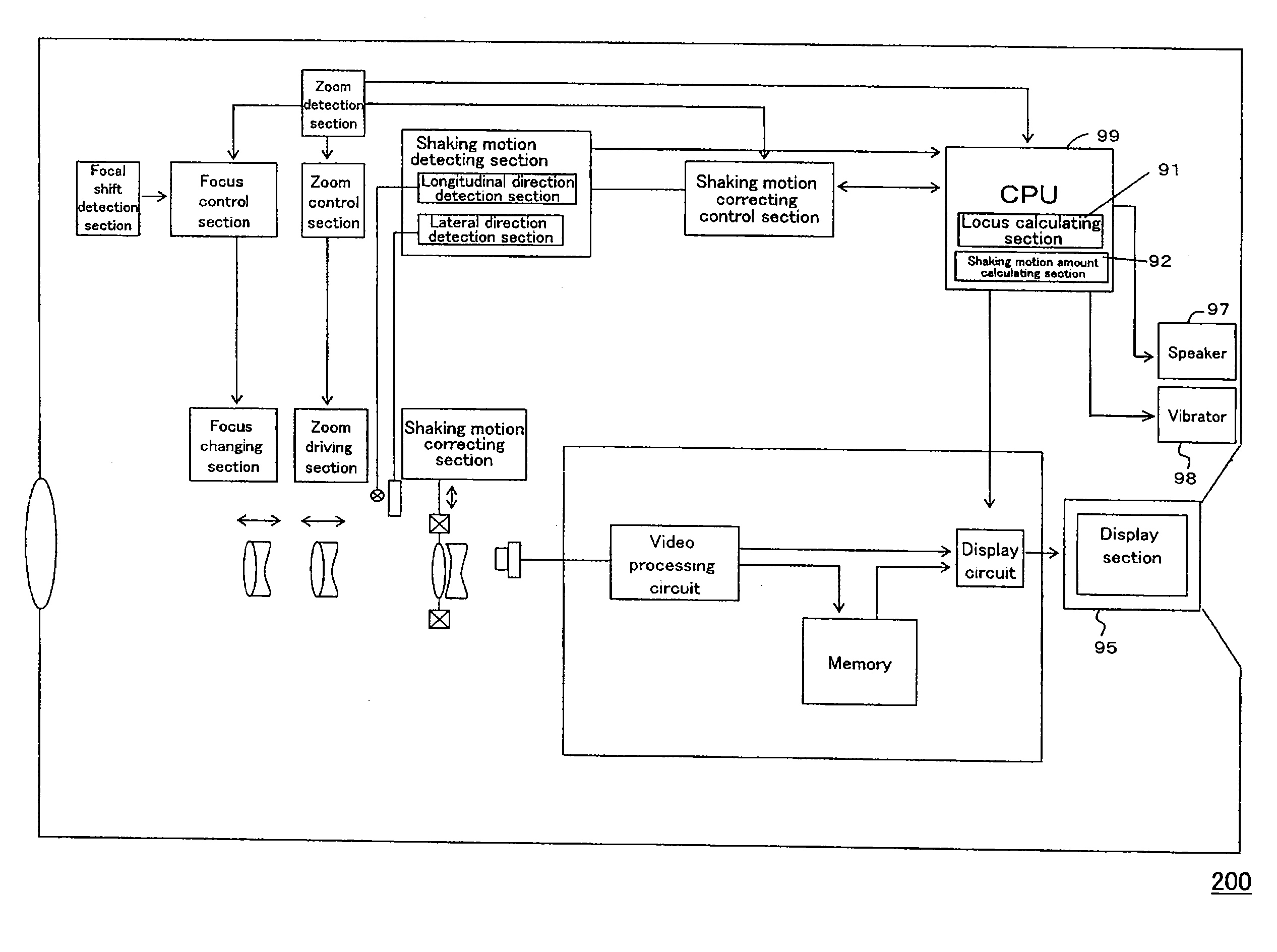
The image pickup apparatus (1) of the present invention includes: a shaking motion detecting section (101a and 101b) for detecting a shaking motion of the image pickup apparatus (1) and for outputting a shaking motion detection signal indicating the shaking motion of the image pickup apparatus (1); an image forming section (2, 2a, and 2b) for forming an optical image by focusing light incident to the image pickup apparatus (1); an image pickup section (5) for converting the optical image formed by the image forming section (2, 2a, and 2b) into electric video information; and a locus calculating section (91) for obtaining locus information indicating a locus of the shaking motion of the image pickup apparatus (1) based on at least the shaking motion detection signal output from the shaking motion detecting section (101a and 101b).

Description

TECHNICAL FIELD [0001] The present invention relates to an image pickup apparatus capable of obtaining locus information required for the correction of the shaking motion, a product package including the image pickup apparatus and a recording medium having a program recorded thereon, and a semiconductor integrated circuit. BACKGROUND ART [0002] As a method for correcting the camera shaking of an image, an optical camera shaking correction method and an electronic shaking motion correction method are known (see, for example, Reference 1 below). [0003] The technique using the optical camera shaking correction method is known as a technique for correcting the camera shaking of a static image. [0004] The technique using the electronic camera shaking correction method is known as a technique for correcting the camera shaking of a moving image. This technique does not require any optical driving section. Therefore, it is possible to reduce the size of the apparatus. [0005] Reference 1: Ja...

Claims


Application Information

Patent Timeline
Patent Type & Authority Applications(United States)
IPC IPC(8): H04N7/18G03B5/00H04N5/232H04N101/00
CPCH04N3/1575H04N5/23248H04N5/23287H04N5/23267H04N5/23261H04N23/6815H04N23/6842H04N23/683H04N23/68H04N23/687H04N25/53
Inventor OSHIMA, MITSUAKI
Owner PANASONIC CORP
Learn More