Method for correcting kinematic errors in microscopic vision system

A microscopic vision and motion error technology, applied in image data processing, instruments, calculations, etc., can solve the problems of small object motion position deviation, affecting 3D reconstruction, and not considering the motion transformation relationship of microscopic sequence images, etc., to achieve Avoiding the effect of the corner matching process

Active Publication Date: 2012-12-26
ZHEJIANG UNIV OF TECH
View PDF2 Cites 20 Cited by
  • Summary
  • Abstract
  • Description
  • Claims
  • Application Information

AI Technical Summary

Problems solved by technology

However, since the microscopic motion video in the microscopic vision system is collected by a high-power microscope and a CCD image sensor, there is an obvious movement position offset in the rotational motion of the tiny object, which greatly affects the later 3D reconstruction
[0004] At the same time, the current error correction methods in computer vision are all based on opt

Method used


Image

  • Method for correcting kinematic errors in microscopic vision system
  • Method for correcting kinematic errors in microscopic vision system
  • Method for correcting kinematic errors in microscopic vision system

Examples


Embodiment Construction

[0058] The technical solution of the present invention will be described in further detail below in conjunction with the accompanying drawings and embodiments, and the following embodiments do not constitute a limitation of the present invention.

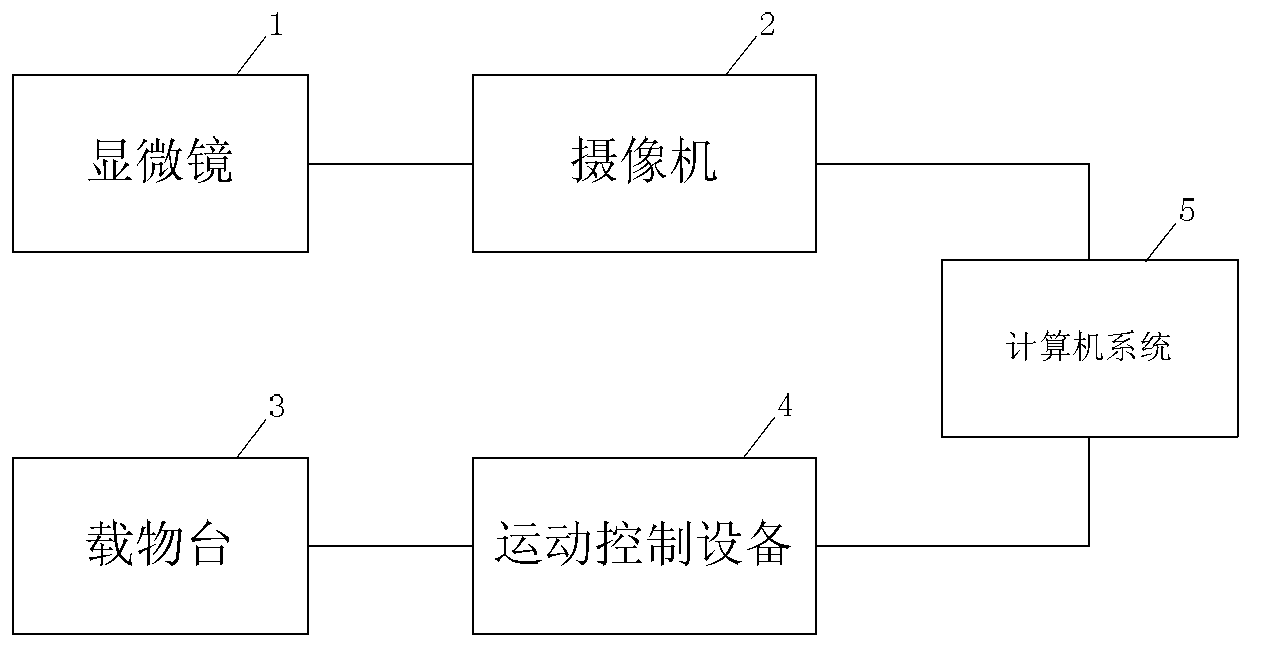
[0059] The micro vision system that the present invention adopts, as figure 1 As shown, it includes a monocular optical microscope 1 and a camera 2, which are responsible for obtaining the microscopic image (or microscopic video) of the observed object; it also includes a stage 3 and a motion control device 4, and the camera 2 and the motion control device 4 are connected To the computer system 5, on the one hand, the computer system 5 controls the stage 3 to rotate at a certain tilt angle through the motion control device 4; The reconstruction method accurately calculates the three-dimensional structure of tiny objects.

[0060] Below to figure 1 As an example, the motion error correction method in the micro vision system of the ...


PUM


Abstract

The invention discloses a method for correcting kinematic errors in a microscopic vision system, which is applied to the microscopic vision system. The method comprises the following steps of: calibrating a camera through a calibration board, establishing a camera model, tracking angular points of the calibration board, generating a tracking trajectory and an ideal revolving trajectory of the angular points through a least square method, then performing error evaluation, establishing an error correcting model, and correcting the microscopic image by virtue of the error correct model. The method provided by the invention can be used for establishing the error correct model for the microscopic vision system only through one-time error evaluation; and the model can be used for any microscopic movement video collected by the system, reducing the movement errors of the system and improving the three-dimensional reconstruction precision, thus being high in practicability.

Description

technical field [0001] The invention relates to the technical field of computer microscopic imaging, in particular to a motion error correction method in a microscopic vision system. Background technique [0002] With the development of signal processing science and computer technology, computer vision as a new field of artificial intelligence has gradually formed and has been greatly developed. Computer vision technology uses cameras instead of human eyes to obtain scene images and convert them into digital signals. Visually perceive and interpret the objective world instead of the human brain. Although it is not yet possible for computers, robots or other intelligent machines to have vision as efficient, flexible and general as humans and other creatures, vision theory and technology have developed rapidly since the 1950s. Helmets are aimed at electronic image stabilization on military vehicles, from image guidance on missiles to military target recognition, computer visi...

Claims


Application Information

Patent Timeline
IPC IPC(8): G06T5/00G06T7/00
Inventor 刘盛翟斌斌金海强陈胜勇
Owner ZHEJIANG UNIV OF TECH
Why Eureka
Try Eureka