Method of making reflector for solar collector or the like, and corresponding product, including reflective coating designed for improved adherence to laminating layer

a technology of solar collectors and reflectors, applied in the field of making reflectors for solar collectors, can solve the problems of optical deficiencies, distortions in the glass on which the coating is applied, and the above-mentioned process of manufacturing reflectors

Inactive Publication Date: 2007-12-20
GUARDIAN GLASS LLC
View PDF54 Cites 44 Cited by
  • Summary
  • Abstract
  • Description
  • Claims
  • Application Information

AI Technical Summary

Benefits of technology

[0006]FIG. 2 is a cross sectional view of a typical mirror used in conventional solar collector systems. The mirror of FIG. 2 includes a reflective coating 7 supported by a bent glass substrate 9, where the glass substrate 9 is on the light incident side of the reflective coating 7 (i.e., the incident light from the sun must pass through the glass before reaching the reflective coating). This type of mirror is a second or back surface mirror. Incoming light passes through the glass substrate 9 before being reflected by the coating 7; the glass substrate 9 is typically from about 4-5 mm thick. Thus, reflected light passes through the glass substrate twice in back surface mirrors; once before being reflected and again after being reflected on its way to a viewer. Second or back surface mirrors, as shown in FIG. 2, are used so that the glass 9 can protect the reflective coating 7 from the elements in the external or ambient atmosphere in which the mirror is located (e.g., from rain, scratching, acid rain, wind-blown particles, and so forth).

Problems solved by technology

Unfortunately, the aforesaid process of manufacturing reflectors is problematic for at least the following reasons.
First, the hot bending (using temperatures of at least 580 degrees C.) may cause distortions in the glass on which the coating is applied, which can lead to optical deficiencies.
Second, application of a reflective coating onto a pre-bent glass substrate is difficult at best, and often leads to reduced reflective / mirror quality.

Method used


Image

  • Method of making reflector for solar collector or the like, and corresponding product, including reflective coating designed for improved adherence to laminating layer
  • Method of making reflector for solar collector or the like, and corresponding product, including reflective coating designed for improved adherence to laminating layer
  • Method of making reflector for solar collector or the like, and corresponding product, including reflective coating designed for improved adherence to laminating layer

Examples


Embodiment Construction

[0032]Referring now more particularly to the accompanying drawings in which like reference numerals indicate like parts throughout the several views.

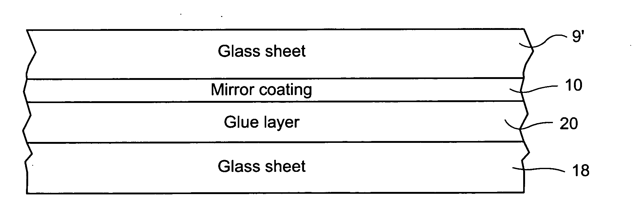
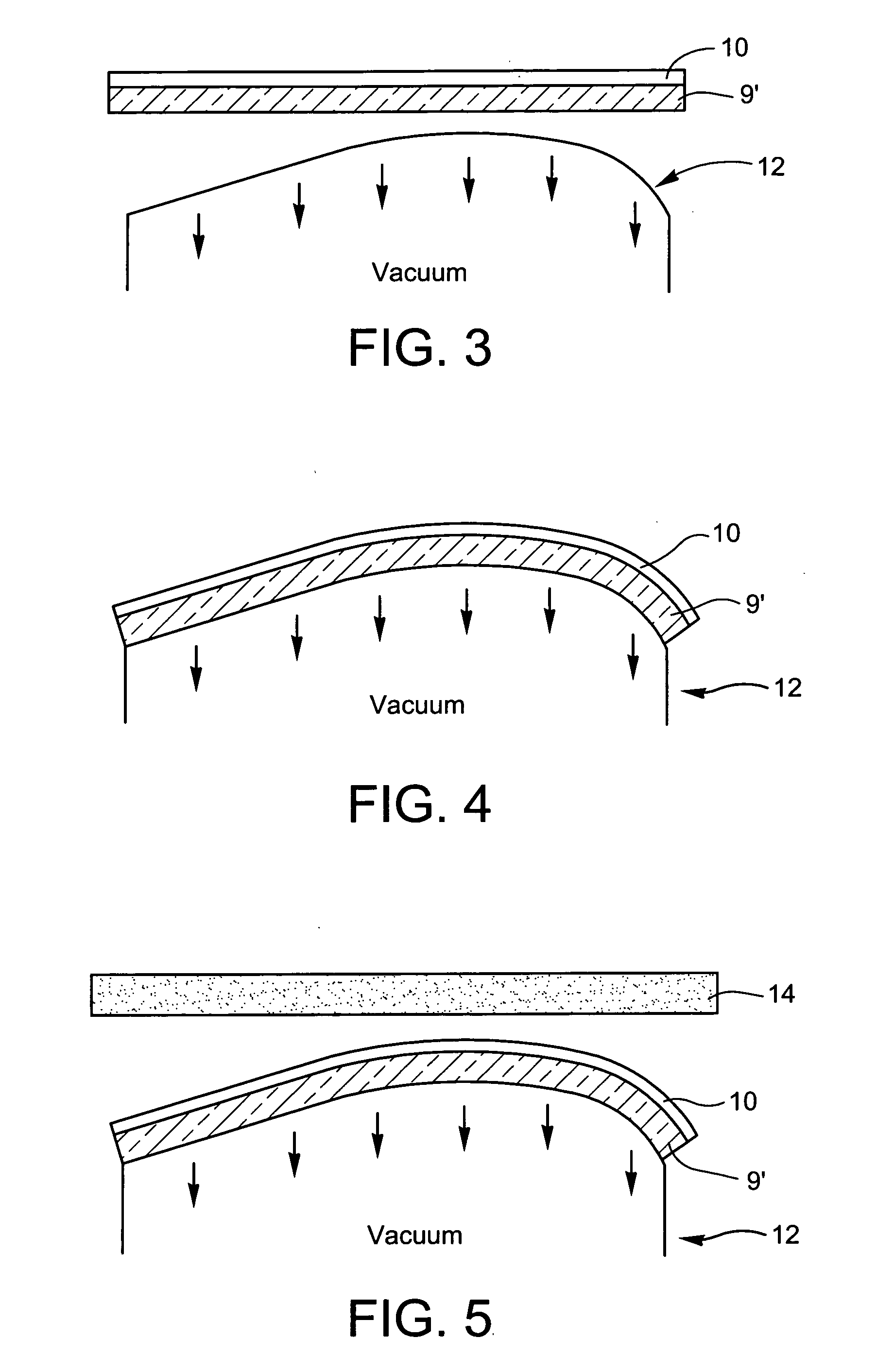
[0033]In certain example embodiments of this invention, a reflector for a solar collector or the like is made by (a) forming a reflective coating on a flat glass substrate, (b) cold-bending the glass substrate with the reflective coating thereon using a mold member; and (c) applying a plate member to the cold-bent glass substrate, the plate member for maintaining the coated glass substrate in a bent orientation. The plate member may be another glass substrate / sheet in certain example embodiments, or alternatively may be a thermoplastic sheet in other example embodiments. In certain example embodiments of this invention, the glass substrate with the coating thereon may be bent at a temperature of no more than about 200 degrees C., more preferably no more than about 150 degrees C., more preferably no more than about 100 degrees C., even m...


PUM

PropertyMeasurementUnit
thickaaaaaaaaaa
thickaaaaaaaaaa
thickaaaaaaaaaa

Abstract

A reflector (e.g., mirror) for use in a solar collector or the like is provided. In certain example embodiments of this invention, a reflector is made performing at least the following steps: (a) forming a reflective coating on a flat glass substrate, (b) cold-bending the glass substrate with the reflective coating thereon; and (c) applying a plate or frame member (e.g., another glass sheet/substrate, or alternatively a thermoplastic member) to the cold-bent glass substrate, the plate or frame member for maintaining the coated glass substrate in a desired bent orientation. In certain example embodiments, the reflective coating is a mirror coating and includes a passivating film including tin oxide and/or silane(s) for better adhering to the polymer based glue/adhesive/laminating layer which may be made of polyvinyl butyral (PVB) or the like.

Description

[0001]This application is related to U.S. Ser. Nos. 11 / 416,388 and 11 / 387,045, the entire disclosures of which are hereby incorporated herein by reference.[0002]This application is related to a reflector (e.g., mirror) for use in a solar collector or the like. In certain example embodiments of this invention, a reflector for a solar collector or the like is made by (a) forming a reflective coating on a flat glass substrate, (b) cold-bending the glass substrate with the reflective coating thereon using a mold member; and (c) applying a plate member (e.g., thermoplastic or glass based) to the cold-bent glass substrate, the plate member for maintaining the coated glass substrate in a bent orientation. In certain example embodiments of this invention, the reflector may be used in a solar collector, or in any other suitable application.[0003]In certain example embodiments, the reflective coating is specially designed to as to better adhere to a polymer based adhesive / laminating layer tha...

Claims


Application Information

Patent Timeline
Patent Type & Authority Applications(United States)
IPC IPC(8): G02B5/08
CPCF24J2/1057Y02E10/40G02B5/0841B32B17/10036B32B17/1022B32B17/10761B32B17/10889F24S23/82
Inventor WANG, YEI-PING (MIMI) H.
Owner GUARDIAN GLASS LLC
Why Eureka
Try Eureka